 English
 Français
 Deutsch
 euskara
 Русский язык
 Italiano
 Português
 Nederlands
 Polski
 Greek
Greek Lietuva
 Türkçe
 日本語
日本語 한어
한어 中文
中文 தாமில்
 فارسی
فارسی हिंदी
हिंदी Tiếng Việt
 ภาษาไทย
 Pilipino
 Indonesia
 தாமில்


Optical Measurement of Narrow Holes
General
Measuring deep and narrow holes with an aspect ratio of 1:5 (Diameter : Height) has always been a difficult and largely an unsolved problem. This is even more problematic if not only the bottom surface needs to be measured, but also the side walls, which are characterized with very steep angles.
Our non-contact distance sensors use a unique technology which has the largest angular coverage in the market (±85°) and is also co-linear. These advantages enable measurement of the side walls as well as the bottom surface.
Some applications require measurement of 90° falling walls. This can be solved by integrating two ConoPoint-10 sensors each tilted at ±7° relative to the top surface, which can accurately measure the walls and return the inner diameter within micron level.
Case Study of Silicon Shower Head
1. This report summarizes the scans and analysis done on Silicon Shower Head of semiconductor components.
2. The objective was to measure the depth of the holes in the wafer until reaching the neck diameter of 0.5mm, and demonstrating the abilities of Optimet sensors at achieving the measurement of the entire hole up to that neck.
3. In order to filter out multiple reflections from the hole slopes but still receive good data from the points that were scanned, we've added a few mechanical and optical elements which clean the signals from the multiple reflections and can see both the top reflective surface (which has also a diffusive signal in it) and into the hole in one scanning session. The use of these elements is possible only due to Optimet's unique capabilities and technology, and increase the measurement accuracy without reducing the measurement range.
4. The scans were performed using a CP-10 with optical filter and 50mm lens with QWP (Quarter wave plate) on Optimet’s laboratory demonstrator scanner as depicted in figure 1.
5. Since the angular coverage of Optimet sensors with that configuration is ±85° and the request was to get a FULL ±90° angular coverage of the hole’s walls it was necessary to tilt the sample by ±7° (2 different tilts, one in each angle) to ensure a full measurement of the hole’s side walls.
6. In order to confirm the accuracy of our scan results we’ve made impressions of various holes of the wafer and measured them for comparison as depicted in figure 2.
Customer requirement
1. Measure height from top surface to where the hole reaches minimum diameter of 0.5mm.
2. Measure up to ±90° of hole’s walls.
Test Set Up
1. An impression of various holes was taken and measured using CP10 with Optical filter and 50mm lens. (we used the same sensor configuration and the scans of the wafer for comparison)
2. The wafer was scanned at the same hole the impression was taken from.
3. The scans on the wafer were taken in 3 different angles: 0°, +7° and -7° as shown in pictures below.
4. The analysis was done in 2 stages:
a. On each of the scans separately by using Optimet’s Viewer SW to measure angle, height and hole diameter
b. By combining two scans, the +7° and -7°, and aligning them together, and then measuring the minimum hole diameter using GeoMagic SW
Sensor parameters:
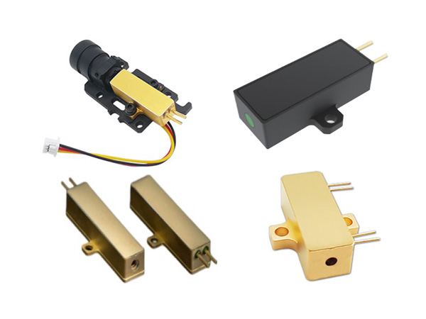
• Type: ConoPoint-10
• Lens: 50mm with QWP
• Other elements: Optical filter
Main sensor specifications:
Lens type: 25mm
Measurement range (mm): 6
Standoff (mm): 44
Accuracy (µm): 5
Scanning parameters:
• Lateral resolution [X*Y]: 5μm X 10μm
• Scanning axis: X axis
• Measurement frequency: 3000Hz
• Laser power: Max
• Auto exposure: on
Scanner system:
• Laboratory Conoscan3000
Measurement analysis
Impression scan:
As can be seen in the pictures above, the impression gves very clear data and can be measured up to an angle of 85°, above that angle there is no data. The diameter of the impression at 85° is 0.554mm and the height from th wafer’s surface to that minimum diameter is 3.636mm
Hole scan:
A scan was done on the same hole as the impression above was taken. 2 holes were scanned in order to do a correct alignment when combining the scans:
After combining the scans and tilting them to 0°:
Hole dimensions:
• The slight difference between the impression scan and the wafer’s scan might be due to the difference in the angles measured since by combining the 2 scans of the wafer we were able to reach ±90° (impression only ±85°)
• The difference between nominal diameter from customer (0.5mm) and actual diameter measured might be due to inaccuracies in alignment of the 2 scans.
In order to try and get a more accurate alignment of the 2 scans we used GeoMagic SW. the results are presented in the following
pictures:
• As can be seen from the pictures above, the hole’s dimensions are the same as measured before: 0.552mm diameter
• The 2nd hole has a diameter of 0.563mm, but I didn’t take an impression of it so I can’t compare. (The neck might be deeper than the first hole and is either out of WR or I didn’t tilt the wafer to a steep enough angle to reach the 90° wall)
Results
1. Requirements:
a. Measure height from top surface to where the hole reaches minimum diameter of 0.5mm – Accomplished. Diameter measured: ~0.55mm.
b. Measure up to ±90° of hole’s walls - Accomplished.
2. As seen from the pictures above, the CP-10 with optical filter and 50mm lens is fully capable of measuring the requested diameter even if it’s >3.5mm deep. That gives an aspect ratio of 1:7 – the largest in the market by far!
3. Suggestion for this application :
Use 2 ConoPoint-10 sensors at which each sensor is tilted 5°-7° compared to the sample’s top surface as shown in the illustration below (need to ad optical filters):
Each sensor will cover the steep angles of the other wall, so one wall will always be deeper than the second. Then the profiles need to be tilted to align the top surface to 0°, and then correlate both scans to find where the neck reaches 0.5mm.
Written by Roei Yiftah, Moshe Danziger and Shmulik Barzilay. Fore more information, please click here.