 English
 Français
 Deutsch
 euskara
 Русский язык
 Italiano
 Português
 Nederlands
 Polski
 Greek
Greek Lietuva
 Türkçe
 日本語
日本語 한어
한어 中文
中文 தாமில்
 فارسی
فارسی हिंदी
हिंदी Tiếng Việt
 ภาษาไทย
 Pilipino
 Indonesia
 தாமில்


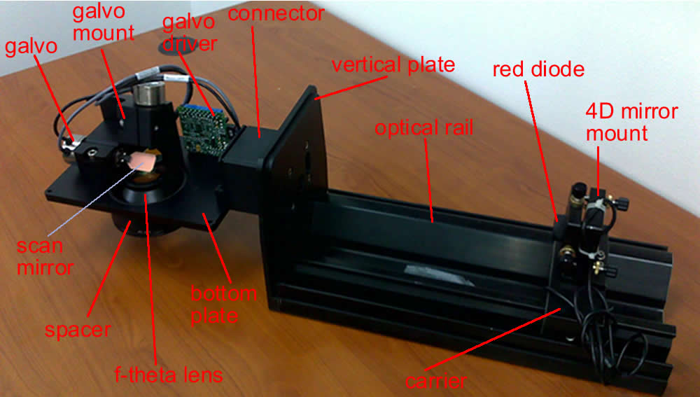
Structure of Laser Marking Head
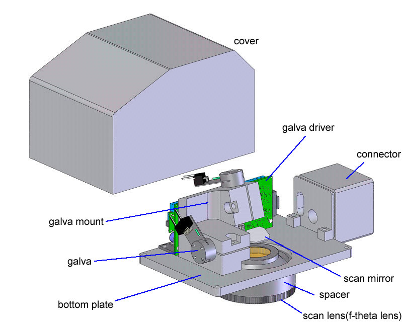
A laser marking heads consists of the following parts:
Galva + driver (board)
Mirror + mirror holder (related to wavelength)
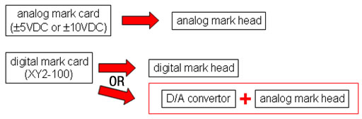
Control card (marking card) with software
D/A card (is needed if the output of the control card is digital)
F-theta lens (spacer or called adaptor is needed if the space/distance between the f-theta lens and scan mirror is not matched) (related to wavelength)
beam expander is needed if the laser beam diameter and the input aperture of the marking head (mirror) is not matched. (related to wavelength)
Mark head mounted with scan lens:
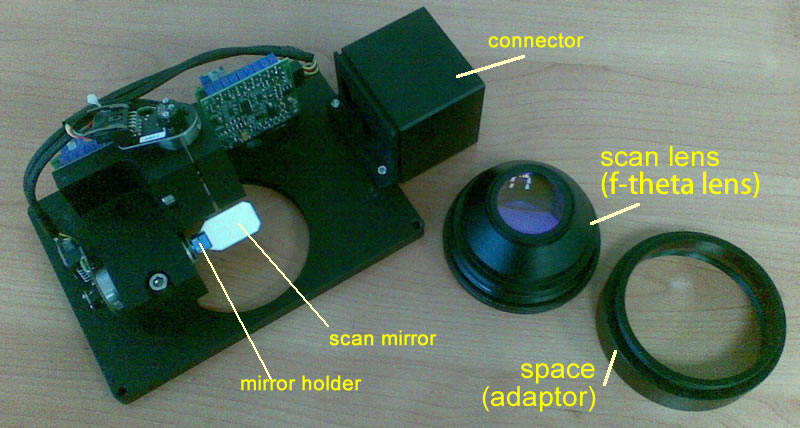
Depending on the design, the scan lens may touch with scan mirror. Thus a spacer may be needed to increase the spacing between the scan mirror and the f-theta lens.
Scan lens mounted with scan lens adaptor:
![]()
Experimental setup:
If you want a laser marking head, please tell us full information on your laser parameters (laser wavelength, laser power, beam diameter), beam expander (expansion ratio), required input beam diameter to the marking head, marking area/field for our recommendation.