 English
 Français
 Deutsch
 euskara
 Русский язык
 Italiano
 Português
 Nederlands
 Polski
 Greek
Greek Lietuva
 Türkçe
 日本語
日本語 한어
한어 中文
中文 தாமில்
 فارسی
فارسی हिंदी
हिंदी Tiếng Việt
 ภาษาไทย
 Pilipino
 Indonesia
 தாமில்


Laser Mask-Making Technology
Laser Mask-Making Technology
Successive generations of semiconductors have necessitated increasingly more advanced technologies to produce the desired densities, speeds and other functions. Optical lithography is, however, still the primary lithographic process for the fabrication of micro-electronics devices. A key component in optical lithography is the photomask. Therefore, mask-making is an essential operation in the manufacture of printed circuits, micro-electronics and optoelectronic devices, and semiconductor integrated circuits using a photolithographic technique. Advances in the degree of integrity must be supported by the mask-making progress, and the characteristics of devices depend highly on the quality of the mask used. Thus, mask-making technology is one of the key technologies in manufacturing micro-electronics devices.
There are many approaches for mask-making such as optical lithography, E-beam lithography, ion beam lithography, and laser mask-making. At present, photomask technology transfers from optical steppers in the 1960s and 1970s to electron beam in the 1980s and laser beam pattern generators in the 1990s. The laser technology involves more tightly controlled processes, and uses the phase-shifting technique. The evolution is in the direction of deep UV, x-ray and phase shift masks. The design rule reaches 0.1 mm, and silicon wafer is 250 to 300 mm in diameter. Table 1 shows the trends of the photomask-making technology.
Table 1 Photomask technology trends
1960s | 1970s | 1980s | 1990s | |
Lithography | Manual & optical stepping | Optical stepping | Optical stepping & E-beam | E-beam & laser beam |
Defect Inspection | Manual | Automatic die-to-die | Automatic die-to-die & die-to-database | Automatic die-to-database & die-to-die |
Critical Dimension (CD) Inspection | Manual white light microscope | Manual & automatic white light microscope | Automatic white light microscope | Automatic focused laser U.V. microscope |
Repair | Chemical & sputter | Manual laser & sputter | Automatic laser | Automatic focused ion beam & laser |
Registration Inspection | Manual compactor | Manual comparator | Automatic XY & manual comparator | Automatic XY |
Particle Protection | No pellicle | No pellicle | Pellicle & manual inspection | Pellicle & automatic inspection |
1. Conventional Mask-making Techniques
A photomask consists of a patterned opaque film such as chrome or iron oxide on a transparent substrate such as glass or quartz plates. Mask-making is a process to selectively remove the film. The need for fabricating integrated circuits has stimulated development in all photolithographic techniques including micro-photography to make reticules, high-resolution emulsions, positive and negative photoresists, proximity and projection printing, deep ultraviolet and x-ray exposure, ion implantation, low-energy sputtering and plasma etching processes. Computer aided design has made very complicated mask patterns feasible without excessive penalties from low-production yield.
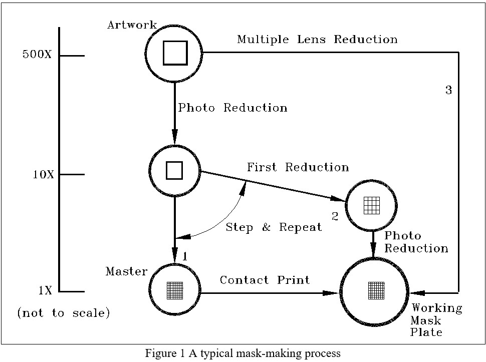
Mask-making began optically. Early hard-surface mask-making was performed using optical pattern generators to make reticles that were reduced and stepped to make 1´ masks. Thus, conventional mask-making uses photoreduction lithography. Most photomasks were made from low-energy sputtered chrome films and non-contact printing was developed to avoid damage from wafer spikes to the fine line images. A typical mask-making process is shown in Figure 2.8. The original mask artwork may be drawn at higher magnifications. A subsequent photographic reduction (generally two-step photographic reduction), using a high-resolution plate for the reticles, is required before the final 10´ reduction with the step-and-repeat camera. This multiple image photographic master is then contact printed, through a submaster, to produce an actual working mask plate having a chrome pattern on a glass substrate suitable for use in a wafer photocopying machine. The next steps are inspection and defect repair. It is obvious that many steps are involved in the production of working photomasks. Exploring new approaches and simplifying the mask-making process have led to the development of many new technologies, one of which is laser mask-making.
2. Laser Mask-Making Techniques
There are three major laser mask-making techniques. The first is to directly remove the thin films of the photomasks (laser engraving). The second is to use laser beams as the light source to expose photoresists covered on the photomasks (laser-based lithography). The third is to generate patterns on the photomasks via photoresist (laser pattern generation).
2.1 Laser Engraving
Laser engraving or direct removal of thin films for specific applications have been reported in the literature. The focused laser beam is moved across the substrate and turned on and off at the appropriate positions to create patterns on the photomask substrate. The removal of film layers involve several interactions: absorption of laser radiation by the film, absorption and reflection of laser radiation by underlying dielectric films or by the substrates, heat transfer from film to substrate, plasma coupling and/or explosive effects.
Currently, there are three models to describe film-removal mechanisms from the zone of light interaction. The first is an evaporation model, which in a sense is identified with sublimation. The second adopts film melting and melt flow under the action of surface-tension forces as the film-removal mechanism. In such a model it is assumed that the initial hole at the centre is formed by evaporation, while its final size is determined by the melt flow to the edges of the zone irradiated. The last is a two-phase model based on the supposition that the removed material appears in two phases - vapour and liquid. All the models had their experimental support, but none of them could accurately explain all the experimental data. Many details of the mechanisms remain unclear, but laser beam removal of film material has widely been used. Therefore, people often perform tests to get optimal combinations of the processing parameters instead of the theoretical prediction for the specific applications.
Typically, a Q-switched Nd:YAG laser is used to selectively remove chrome and iron oxide from glass substrates at the wavelengths of 1064 nm and 532 nm, respectively. The system is composed of a laser generator, a beam expander, a focusing lens, and a beam scanner or an X-Y table [2.114]. The Nd:YAG laser has a pulse width in the order of ns and a Gaussian beam distribution of TEM00 mode. The required laser repetition rate is matched to machining speed to meet the requirement of a constant pulse to pulse overlap. For example, the pulse to pulse overlap is greater than 50 percent if the laser is pulsed at intervals of 2.5 mm, and the machining speed is between 5 mm/sec and 20 mm/sec. A beam expander is needed to reduce the beam divergence angle so as to reach the smaller focal spot size.
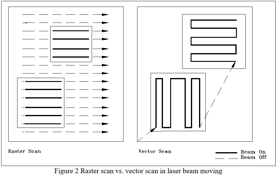
The pattern can be created by scanning the laser beam or moving the photomask through a CNC controlled X-Y table. There are two scan techniques, raster scan and vector scan, as shown in Figure 2.9. Raster scan is best suited for generating complex patterns of many geometries. The starting position of each scan line is a pre-set position away from the geometry, and then laser beam moves along one axis (for example, x axis). When the beam reaches the position where the pattern is to be generated, the laser is pulsed until the beam reaches the position where the pattern is not to be created. The scan line terminates at the end of the geometry. Then, another axis (for example, y axis) is given an incremental motion equal to the resolution, and the second scan line starts. All the areas will be scanned in the similar way. The fundamental difference between the vector scan and the raster scan is that only the pattern area to be created is addressed or “vectored to” in the vector scan. In fact, vector scan is in the “writing” mode like laser marking. The machining trace is along the required pattern. The software for such a system is similar to word processing and CAD/CAM software. Thus, it is easy to use with such powerful features as line, arc, circle, and alphanumerics. This technique is best suited for patterns with simple geometries. The photomask can be generated quicker by vector scanning for sparsely distributed geometries.
One of the main advantages of laser engraving is that no further processing of the photomask is required. It is a one-step process. The main limitations are: only negative images can be generated by micro-machining; slightly scalloped edges are produced; and fabrication time is longer than fabricating masks by exposing photoresist.
Another important application of this technique is to repair opaque defects on chrome masks. The main lasers used in the mask repair are Nd:YAG lasers or 2nd- or 4th harmonic YAG lasers, argon lasers and excimer lasers. Laser repair tools are capable of repairing all visible defects in submicron mask geometries. The details will be described in the following section.
2.2 Laser-based Lithography
Laser-based lithography is similar to a conventional reduction stepper. In this case, the laser beam is passed through a reticle projected onto the photomask housed in an environmental chamber and reticle pattern is replicated in parallel.
Conventional lasers are not suitable for laser-based lithography. The term “conventional” is meant to apply to those lasers whose output beams are highly coherent, both temporally and spatially. The high degree of coherence - especially spatial coherence - of conventional lasers has historically rendered them unattractive for use in high resolution lithography due to the problem of speckle. In illumination of an object with a spatially coherent wavefront, any scattering at an optical surface causes different segments of the wavefront to interfere constructively and destructively at the sample surface and generate a random pattern called a speckle. This problem has limited the ways in which coherent lasers can be used for creating fine-line patterns. However, excimer lasers can be used because the coherence lengths are negligible and operate more like a light bulb with highly-collimated light. Exposure with excimer lasers has the advantages of high intensity, short exposure time, and short-wavelength. The high output power of excimer lasers makes it possible to obtain high mask throughputs. As the lithographic resolution is linearly proportional to the wavelength, the short-wavelength radiation with excimer lasers has improved the resolution of optical photolithography to the submicron range.
Several lithographic exposure techniques, e.g., contact, full-wafer scanning projections, and step-and-repeat projection, have been explored with excimer lasers.
2.3 Laser Pattern Generation
Laser pattern generation is actually maskless lithography, similar to electron beam lithography. The focused laser beam exposes the photoresist directly. The processing system is similar to that in laser engraving, in which the focused laser beam is radiated directly on the film instead of the photoresist.
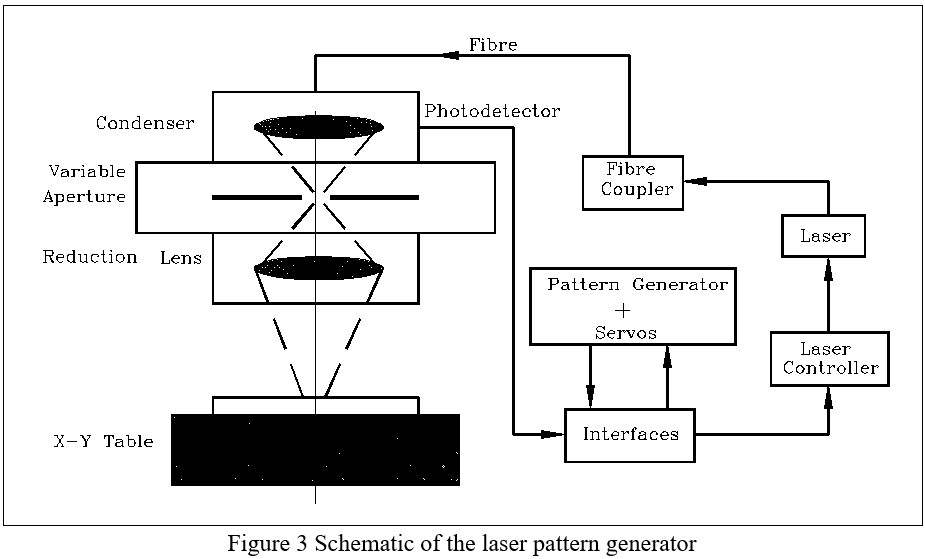
Generally speaking, there are two types of lasers used in exposing photoresist: UV wavelength lasers (such as XeCl excimer laser at 308 nm wavelength) and visible wavelength (such as Ar+ laser at a wavelength of 488 nm, and He-Cd laser at a wavelength of 442 nm). A typical schematic of the system is shown in Figure 2.10. It is noted that the variable aperture is very important. Under computer control, the aperture is driven to the required exposure size and the X-Y stage to the required positions. The illumination source projects the image of the aperture through a reduction lens onto the photomask blank coated with photoresist. Because of high intensity and short exposure time, the “expose on the run” can be operated, namely, making an individual resist exposure only requires a single laser pulse. Therefore, the processing speed is higher than those obtained using other lithographic tools such as the mercury arc lamp illumination source. It is reported that the throughput can reach a maximum of 460,000 exposures per hour.
One of the main considerations in laser pattern generation is the chemistry of the photoresists. Different photo-resists respond differently at different wavelengths. For example, the standard g-line resists such as AZ1350 and Shipley 1800 have poor response to 308 nm because laser pattern generation requires that the resist layer be sensitive and relatively transparent to the laser light. But the i-line (365nm) resist performs the best at 308 nm, therefore, AZ 5200 and UCB/JSR 1X500EL are used routinely. For exposing photoresist with a CW argon ion laser, KTI 605 negative photoresist and Shipley 1400-17 positive photoresist are used and linewidths of 5 to 20 microns have been achieved
2.4 Advantages of Laser Mask-Making
Conventional mask-making methods include material deposition, diffusion and etching. All these processes are complicated and unreliable. At present, lasers have been used to make the masks more efficiently. Compared to the conventional methods, laser mask-making provides the following advantages:
(1) Good potential in micro-processing, particularly in the micron order;
(2) High efficiency and low operation cost;
(3) Non-contact processing and no special working environmental needed;
(4) Easy to automate and integrate (direct writing of patterns can be established using computer-controlled movement of the beam or sample);
(5) Precise beam positioning and a highly localised energy transfer to the workpiece (a narrow damage zone); and
(6) Contamination free.
However, laser process parameters must be optimised in order to obtain good quality. The study of engraving mechanisms will further enhance the understanding of this complicated process.
2.5 Comparison of Laser and E-beam Mask-Making
As mentioned before, the more stringent requirements for the photomasks have dictated the technology shift from optical steppers to electron-beam and laser beam. Comparing the two mask-making technologies, it is found that current laser pattern generators show better CD uniformity and butting characteristics, and e-beam systems offer better resolution and corner definition. However the two technologies give essentially comparable image placement and edge roughness.
3. Laser Mask Repair
It is hardly possible to have defect-free masks due to the complex mask-making processes. Over 50% of today's 5´ reticles require some sort of repair to meet the zero defect criterion. Therefore, mask repair is an important step in mask-making.
For Cr-coated glass photomasks, the chrome-related defects are generally classified into two types: opaque (excess chrome) and clear (missing chrome). Opaque defects include pin-spots, Cr bridges, protrusions, and excess Cr patterns. Clear defects include pin-holes, intrusions, breaking, and missing Cr patterns.
For conventional opaque mask repair, the procedures are similar to those used in fabricating the mask, namely, (1) application of photoresist to the defective portions, (2) exposure of defective portions with an appropriate laser beam energy, (3) development, (4) etching, (5) removal of the resist, (6) washing and drying, and (7) inspection. This method requires skilled workers and is time-consuming. For clear defects, there is currently no good and efficient method available for production use. In opaque repair, excess metal defects on the mask absorb the laser energy and are thermally or chemically machined away depending on the laser wavelengths used.
Clear defects are much more difficult to repair than opaque defects because clear defects have to be repaired by depositing materials onto the mask. The deposited materials must cover the pin-holes and must be durable to withstand subsequent washings. Laser micro-chemistry is an effective method for clear defect repair, with which a finely focused laser beam drives a chemical reaction in a localised area. The chemical reaction can be either pyrolytically (by thermal energy) or photolytically (by light energy) driven according to the laser wavelength.
Typically, metal alkyls and carbonyls are used in laser pyrolytic deposition. In general, these are thought to be extremely toxic and too dangerous to handle. However, gas handling technology has evolved to the point where these compounds can be routinely handled in a safe, reliable and efficient manner. It was reported that W(CO)6 and Al(CH3)3 were used in mask repair systems, in which an argon laser (514.5 nm) was employed. The repair process via laser deposition is performed by placing a focused laser spot over the edge of the defect in the presence of organometallic vapour. Organometallic molecules which strike this area are decomposed thus forming a film. Some molecules decompose on the glass forming a thin nucleation layer. This nucleation layer serves as a site for further film growth. The laser beam is moved until the repair is completed. The problem is that the process of pyrolytic deposition is difficult to control and results in non-uniform surface quality.
A more advanced method is the photolytic technique. It makes use of a finely focused UV laser to deposit metallic halides from a gas, onto the substrate through a photolytic reaction (the chemical decomposition by the action of radiant energy). The lasers most commonly used are fourth harmonic UV radiation from a Nd:YAG laser and excimer laser. It was reported that tungsten carbonyl was the most promising candidate based on absorption cross-section at 248 nm, and deposited film quality. However, the problem associated with tungsten carbonyl was that the deposited film had poor adhesion and was usually washed off during rinsing in a high pressure water jet. It was found necessary to add Cr(CO)6 to the process gas to enhance the adhesion of the deposited film to the surface of the photomask. The percentage of Cr(CO)6 in the process gas influences not only the adhesion of the deposited film, but also the properties of the halo that is present after the repairing process.
As mask defects are difficult to eliminate due to the complex fabrication processes, mask repair becomes critical for companies to remain profitable. Laser mask repair is one of the most promising techniques and is under intense R & D world-wide particularly in the area of clear defect repair.
4. Summary
Laser mask-making is a new technology. The processing speed is still a problem in laser engraving compared to projection lithography, but this method is especially suitable for the defect repair of photomasks because the opaque defects need only be vaporised. Short-wavelength radiation with excimer lasers has improved the resolution of optical photolithography to the submicron range. Laser pattern generation has increased the throughput of mask-making.