 English
 Français
 Deutsch
 euskara
 Русский язык
 Italiano
 Português
 Nederlands
 Polski
 Greek
Greek Lietuva
 Türkçe
 日本語
日本語 한어
한어 中文
中文 தாமில்
 فارسی
فارسی हिंदी
हिंदी Tiếng Việt
 ภาษาไทย
 Pilipino
 Indonesia
 தாமில்
Send us a message
CLOSE

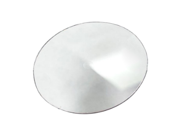


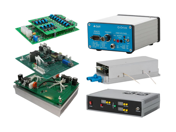
The acousto-optical Q-switch often used in the laser marking makes use of mutual interaction between an ultrasonic wave and a light beam in a scattering medium. The light beam that enters in a direction forming a Bragg angle to the wave surface of the acoustic wave in the scattering medium is diffracted in accordance with periodic changes in the diffraction rate produced by the acoustic wave.
The situation is briefly explained. First of all, an RF signal is impressed to the transducer adhered to the molten quartz and thickness extensional vibration is produced. Ultrasonic shear waves are caused to advance in the molten quartz by this vibration, and phase grating formed by acoustic waves is produced. The laser beam is diffracted when it satisfies the Bragg angle with respect to this phase grating, and is separated in space from the incident light. If the laser optical resonator is constructed against 0-dimensional diffracted light (undiffracted light), the diffracted light deviates from the laser optical resonator axis when a RF signal is impressed. As a result, loss occurs in the laser optical resonator and laser oscillation is suppressed. To make use of this phenomenon, an RF signal is impressed for a certain length of time only (status of low Q-value) to suspend laser oscillation. In the meantime, the population inversion of the Nd:YAG rod is accumulated by continuous pumping. When the RF signal is reduced to zero (status of high Q-value) and the loss to the laser optical resonator is removed, the accumulated energy is activated as laser oscillation in a pulse form within an extremely short length of time. They are Q-switch pulses.
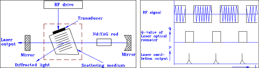
This situation is briefly explained. When an RF signal is subjected to pulse modulation, it is possible to periodically take out a Q-switch pulse. When the period of Q-switch pulses becomes shorter than the life (about 200 ms) of the higher order of the Nd:YAG rod, however, the population inversion decreases and the peak value of Q-switch pulses decreases.
For more information on the principle, please click here.
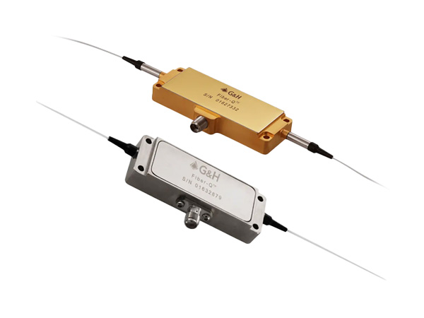
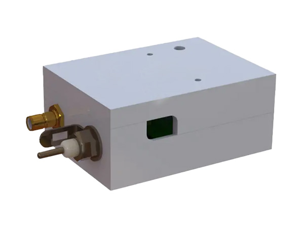
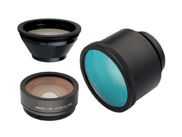
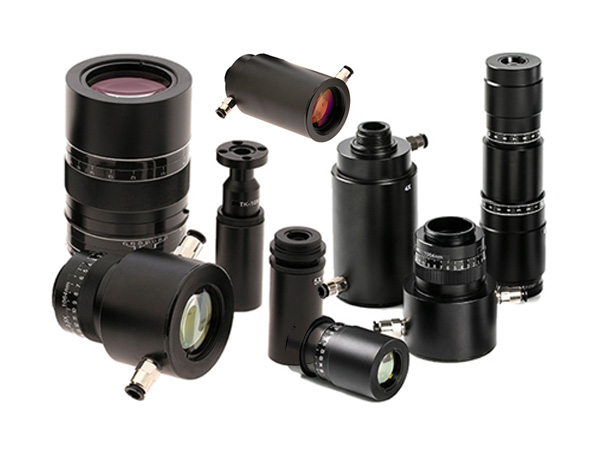
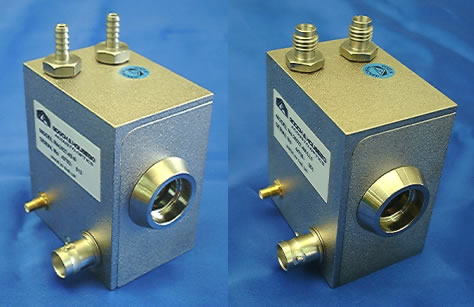
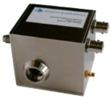
A water-cooled acousto-optic Q-Switch for use in high-power Nd:YAG laser systems. Combining top grade fused silica with high quality optical finishing and in-house anti-reflection coatings, this Q-Switch exhibits very low insertion loss and high damage threshold. Through an innovative design and manufacturing process, RF powers up to 100W may be applied.
Standard options include a choice of frequencies (24 to 68MHz), active apertures (1 to 8mm), acoustic modes (compressional for linear polarisation, shear for unpolarised) and water connectors. Customised housings are available for OEM ’s.
Specifications
Model no: See “Options” below
Interaction medium: Fused silica
Operational wavelength: 1064nm
Anti reflection coating: Hard multi-layer dielectric
- Reflectivity:<0 ·2% / surface ( < 0 ·1% typical)
- Damage threshold: > 500MW cm-2
Insertion loss:<10% ( < 5% typical)
Active aperture: See “Options” below
Diffraction (separation) angle: ~4.8 mrad
VSWR: 1 ·2:1
Maximum CW drive power: 100W
Thermal interlock: +50ºC
Water Cooling
Flow rate: 190cc / min (minimum)
Water Temperature:
- Recommended operating: 32ºC
- Recommended maximum: 40ºC
Water Connectors: See “Options” below
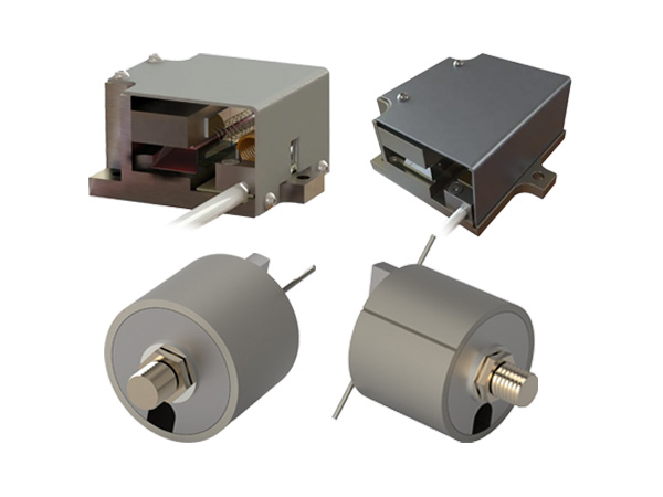
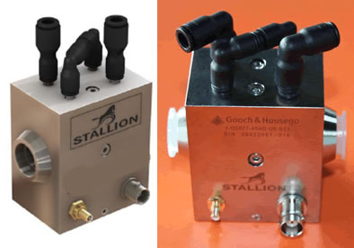
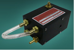
A ‘Stallion ’ version of our industry standard water cooled Acousto-optic Q-Switch, for use in high power lamp or diode pumped Nd:YAG lasers.
The patent pending ‘Stallion ’ manufacturing technique provides superior corrosion resistance whilst maintaining optimum performance and RF power handling capabilities up to 100W.
Combining top grade fused silica with high quality optical finishing and in-house anti-reflection coatings, this Q-Switch exhibits very low insertion loss and high damage threshold.
In addition to the standard product shown, custom configurations are available for specialized applications. These include alternative housing options, wavelengths and RF frequencies.
Key Features:
Industry standard for Nd:YAG lasers
Superior corrosion resistance
Stainless steel cooling channels
High damage threshold
Push fit water-connectors
Up to 100W RF power handling
Custom configurations available
Applications:
Material processing:
Laser marking
Laser engraving
Laser cutting
Laser drilling
Medical (surgery)
Lithography
General Specifications:
| Interaction material: | Fused Silica |
| Wavelength: | 1064nm |
| AR coating reflectivity: Damage threshold: | < 0.2% per surface > 1GWcm-2 |
| Transmission (single pass): | > 99.6% |
| Static insertion loss: | ≤ 6% at 50W laser power |
| VSWR: | < 1.2:1 (<1.4:1 at 50W RF power) |
| RF power rating: | 100W CW (max) |
| Water flow rate: | > 190cc / minute |
| Water-cooling channel material: Recommended water temperature: Thermal switch cut-off: | Stainless steel 316 +22oC to +32oC +55oC +/- 5oC |
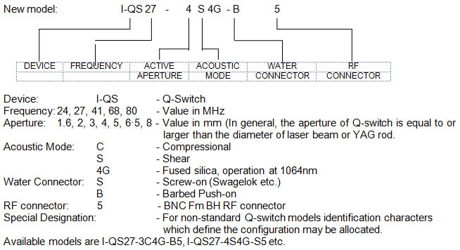
Ordering Codes: Example: I-QS027-4S4G-N5-ST1 (Q-Switch, 27.12MHz, 4mm active aperture, shear mode, fused silica, 1064nm, 4mm OD straight push fit water-connectors, BNC, Stallion housing with M3 mounting holes)
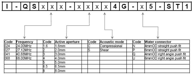
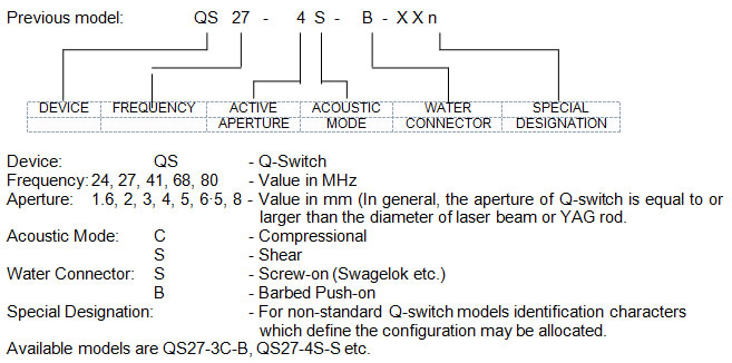
To find the frequency of the RF driver (Q-switch driver).
To find the diameter of the YAG rod or laser beam diameter from the laser head. In general, the aperture of the Q-switch is 1mm larger than the YAG rod diameter.
If there is no polariser inside the laser resonator and the laser beam is non-polarised, acoustic mode S should be used. Otherwise, acoustic mode C is used in polarised laser beam. (Remark: the above recommendation is not 100% true. We have found that acoustic mode S is also used in polarised lasers and it operates well. Acoustic mode C is also used in non-polarised lasers and it operates well too.)
Then to select a suitable water connector. Please note that you can use your own water connector to replace/change the connector since the connector is screwed. For example, if the damaged Q-switch has B-connector and you have a new Q-switch with S-connector, you can take away B-connector from the damaged Q-switch and then install this B-connector into your new Q-switch replacing its S-connector.
The following table shows the RF powers required at the theoretical peak loss modulations for Q-switches:
| Aperture size | Compressional peak RF power | Shear peak RF power |
| 2mm | ~20W | ~60W |
| 3mm | ~25W | ~90W |
| 4mm | ~35W | ~100W |
| 5mm | ~50W | ~100W |
Remark: the maximum allowed RF input is 100W only.
| Stallion, I-QS27 series | Standard QS27-xx-x series |
| Water-cooling pad still made of Aluminum to avoid corrosion (prevent oxidation) | Water-cooling pad is made of Aluminum, no coating. This is very easy to cause corrosion. |
| Inner water-duct is having 3.5mm diameter by coating with stainless steel | Inner water-duct is having 2.5mm diameter |
| Same dimension and screw hole position as QS27 series | |
| Screw is using international standard, M3 | Screw is using old UK standard |
| Water-connector is having choice of right-angle and straight through | Only straight through version |
| Water-connector is having 4mm or 6mm diameter selection | |
| Using laser marking for the serial number on the housing (un-erasable) | Using sticker to label part number and serial number that is very easy to erase even by hand (erasable of the device ’s information) |
| Stallion Q-switch series | Old Q-switch series |
| I-QS27-5S4G-U5-ST1 | QS27-5S-x |
| I-QS27-3S4G-U5-ST1 | QS27-3S-x |
| I-QS27-5C4G-U5-ST1 | QS27-5C-x |
| I-QS27-4S4G-U5-ST1 | QS27-4S-x |
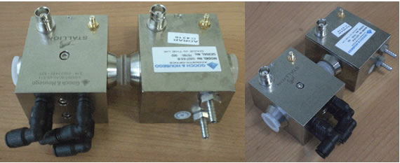
Comparison between Stallion and old Q-switches. The main difference of the outlooks is water connector.
| Model No. | I-QS027-4C10G-x5-ST7 |
| Device | AO Q-Switch |
| Interaction material | Crystal Quartz |
| Wavelength | 1064nm |
| AR coating reflectivity | < 0 ·2% per surface |
| Damage threshold | > 1GW/cm2 |
| Transmission | > 99 ·6% |
| Frequency | 27.12MHz |
| Polarisation | Linear, vertical to base |
| Active Aperture | 4.0mm |
| Acoustic Mode | Compressional |
| Loss Modulation | > 80% |
| Max RF Power | 75W |
| Water flow rate | > 0.2l / minute |
| Recommended water temperature | 22ºC to 32ºC |
| Thermal switch cut-off | 65ºC plusmn; 5% |
| Housing | Stallion, St/St 316 water channels |
| Water connectors | To be specified |
| Model No. | QS027-4J-xxx | I-QS027-5S4Y-x5-ST1 |
| Interaction material | Fused Silica (Infrasil, water-free) | Fused Silica (Infrasil, water-free) |
| Wavelength | 1550nm | 946nm |
| AR coating reflectivity | < 0.2% per surface at 1550nm | < 0.2% per surface at 1550nm |
| Damage threshold | > 500MWcm-2 | > 1GWcm-2 |
| Polarisation | Random | Random |
| Interaction length | 46.0mm | 46.0mm |
| RF frequency | 27.12MHz | 27.12MHz |
| VSWR | < 1.2 1 | < 1.2 1 |
| Acoustic Mode | Shear | Shear |
| Active aperture | 1.6mm | 5.0mm |
| Clear aperture | 8.0mm | 8.0mm |
| Loss modulation | > 70% at 50W; > 85% at 100W | > 75% |
| Housing | Standard QS27-xx-xxx | Stallion |
| Water connectors | Barbed or Screw fit | Push fit |
| Model No. | I-QS041-3C4H-x5-ST1 | QS027-4H-xxx |
| Interaction material | Fused Silica(Infrasil, water-free) | Infrasil (water-free fused silica) |
| Wavelength | 1319 - 1342nm | 1319-1342nm |
| AR coating reflectivity | < 0.2% per surface at 1319-1342nm | < 0.2% per surface |
| Damage threshold | > 1000MWcm-2 | > 1000MWcm-2 |
| Polarisation | Linear (vertical to base)) | Linear (vertical to base) |
| Interaction length | 46.0mm | 46.0mm |
| RF frequency | 40.68MHz | 27.12MHz |
| VSWR | < 1.2 1 | < 1.2 1 |
| Acoustic Mode | Compressional | Compressional |
| Active aperture | 3.0mm | 5.0mm |
| Clear aperture | 8.0mm | |
| Loss modulation | ~ 85% at 40W RF power | > 80% at 50W RF power |
| Housing | Stallion | Standard QS24/27-xx-xxx |
| Water connectors | Push-fit | Barbed |
| Model No. | QS027-4G/M-xxx | QS027-4C/G-xxx |
| Interaction material | Infrasil (water-free fused silica) | Fused Silica |
| Wavelength | 1064nm / 2128nm | 532/1064nm |
| AR coating reflectivity | < 0.2% per surface at 1064nm < 0.3% per surface at 2128nm | < 0.2% per surface |
| Transmission: | > 99.6% at 1064nm > 99.4% at 2128nm | > 99.6% |
| Damage threshold | > 500MW/cm2 | > 500M W/cm2 |
| Polarisation | Linear, vertical to base | Linear, vertical to base |
| Active Aperture: | 5.0mm | 4.0mm |
| Interaction length | 46.0mm | 46.0mm |
| RF frequency | 27.12MHz | 27.12MHz |
| VSWR | < 1.2 1 | < 1.2 1 |
| Acoustic Mode | Compressional | Compressional |
| Active aperture | 5.0mm | |
| Loss modulation | > 85% at 45W (1064nm) > 75% at 100W (2128nm) | > 80% at 35W |
| Rise-time (10-90%): | 109ns/mm | 109ns/mm |
| Housing | Standard QS27-xx-xxx | Standard QS27-xx-xxx |
| Water connectors | Barbed or Screw fit | Barbed or Screw fit |
| Model No. | I-QS027-4S4V2-x5-ST1 | I-QS041-5C10V5-x5-ST3 |
| Device | ||
| Interaction material | Infrasil (water-free fused silica) | Crystal Quartz |
| Wavelength | 1550nm | 1900 - 2100nm |
| Polarisation | Any | |
| AR coating reflectivity | < 0.2% per surface | < 0.5% per surface |
| Damage threshold | > 500MWcm-2 | > 500MWcm-2 |
| Transmission | > 99.6% | > 99.0% |
| Frequency | 27.12MHz | 40.68MHz |
| Active Aperture | 4.0mm | 5.0mm |
| Acoustic Mode | Shear | Compressional |
| VSWR | < 1.2:1 (<1.4:1 at 50W RF power) | < 1.2:1 (<1.4:1 at 50W RF power) |
| Loss Modulation | > 60% | 70% |
| Max RF Power | 100W | 50W |
| Water flow rate | > 0.2l / minute | > 0.2l / minute |
| Water cooling channel material | Stainless steel 316 | Stainless steel 316 |
| Recommended water temperature | +22oC to +32oC | +22oC to +32oC |
| Thermal switch cut-off | +55oC +/- 5oC | +65oC +/- 5oC |
| Storage temperature | 0 to +50degC | -20 to +70degC |
| Model No. | QS027-4M-AP1 | QS027-4H-xxx |
| Interaction material | Fused Silica (Infrasil, water-free) | Fused Silica (Infrasil, water-free) |
| Wavelength | 1980 - 2050nm | 1342 / 1550nm |
| AR coating reflectivity | < 0.2% per surface at 1980 - 2050nm | < 0.2% per surface at 1342nm < 0.5% per surface at 1550nm |
| Damage threshold | > 500MW/cm2 | > 500M W/cm2 |
| Polarisation | Linear (vertical to base) | Any |
| Active Aperture: | 4 ·0mm | 1.6mm |
| Interaction length | 46 ·0mm | |
| RF frequency | 27.12MHz | 27.12MHz |
| VSWR | < 1.2 1 | < 1.2 1 |
| Acoustic Mode | Compressional | Compressional |
| Loss modulation | ~ 55% at 50W (3mm beam diameter) | 70% at 50W RF power > 85% at 75W RF power |
| Rise-time (10-90%): | 109ns/mm | 109ns/mm |
| Housing | Standard QS27-xx-xxx | Standard QS27-xx-xxx |
| Water connectors | Barbed or Screw fit | Barbed or Screw fit |
| Model No. | I-QS050-1.4V10M-U5-HI10 | I-QS027-5C4G-x5-SOx |
| Interaction material | Crystal Quartz | Fused Silica |
| Wavelength | 2053nm | 1060-1125nm |
| AR coating reflectivity | < 0.2% per surface | < 0.3% per surface |
| Polarisation | Linear (vertical to base) | Linear, vertical to base |
| Active Aperture: | 1.4mm | 5mm |
| Interaction length | 46 ·0mm | |
| RF frequency | 50MHz | 27MHz |
| VSWR | < 1.2 1 | |
| Acoustic Mode | Very High Efficiency (VHE) | |
| Loss modulation | >95% | > 80% |
| Housing | Stallion | Stallion |
| Water connectors | Push in | Push in |
| Model No. | QS027-10M-NL5 | I-QS027-4C10V5(BR)-x5-IS6 |
| Interaction material | Crystal Quartz | Crystal Quartz |
| Wavelength | 2054nm | 2000-2100nm |
| AR coating reflectivity | < 0.2% per surface | < 0.2% per surface |
| Polarisation | Linear (vertical to base) | Linear (vertical to base) |
| Active Aperture: | 5mm | 4mm |
| Interaction length | 46 ·0mm | 46 ·0mm |
| RF frequency | 27.12MHz | 27MHz |
| VSWR | < 1.2 1 | < 1.2 1 |
| Acoustic Mode | Compressional | Compressional |
| Loss modulation | ~ 80% at 100W | >80% |
| Rise-time (10-90%): | 109ns/mm | 109ns/mm |
| Housing | Standard QS27-xx-B | Stallion |
| Water connectors | Barbed | Push in |
The surface of the crystal inside Q-switch should be kept clean and dry. If the surface is contaminated, the surface will easily be burnt due to high power laser beam.
The cooling water should be de-ionised water or distilled water for QS series Q-switches. Please do not use city water as cooling water. Otherwise, the cooling channels will be corrupted and then the Q-switch will be damaged.
The damage caused by non-proper use is not within the warranty.
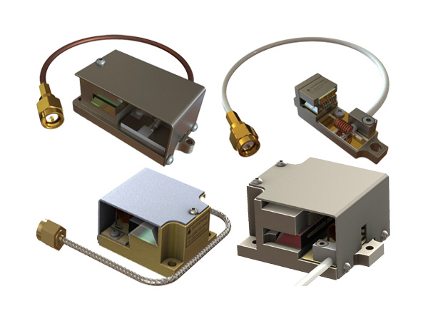
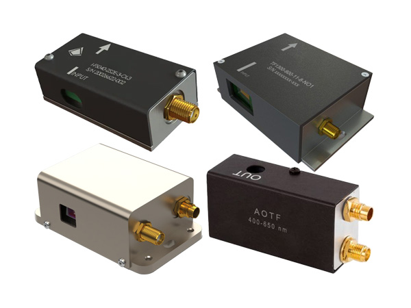
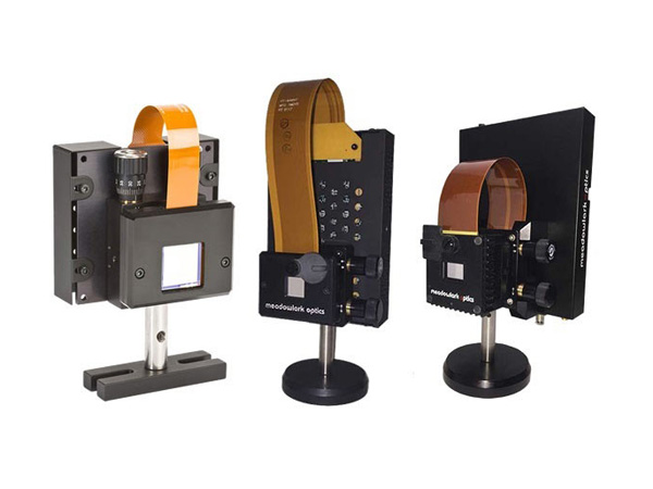
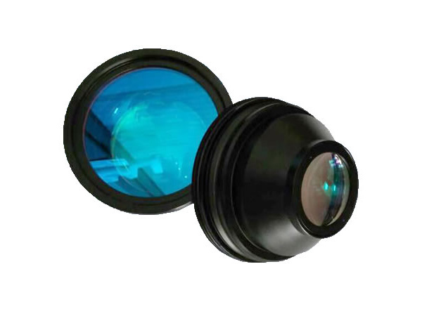
STBR series Acousto-Optic Q-switching systems for industrial and laboratory applications. The STBR free space Q-switches are designed for the highest conversion efficiency of RF energy into acoustic energy by attaching the transducer to the crystal with an advanced vacuum metallized process. Q-switches are special modulators designed for use inside laser cavities. They are fabricated from high optical quality Fused Quartz, Flint Glass, and Tellurium Dioxide, or other acousto-optic materials with Brewster cut optical faces or durable hard oxide AR coatings for high optical power applications.
| Model # | FSQ-24-2-BC | FSQ-27-5-BC | FSQ-80-5-BC | TEQ-27-4-BC | TEQ-80-20-BC |
| Substrate | SiO2 | SiO2 | SiO2 | TeO2 | TeO2 |
| Brewster cut | yes | yes | yes | yes | yes |
| Laser Wavelength (nm) | 1064 | 1064 | 1060 | 2940 | 800 |
| Active Aperture (mm) | 2 | 2 | 1 | 1.5 | 3 |
| Center Frequency (MHz) | 24 | 27 | 80 | 27 | 80 |
| Digital Modulation Bandwidth (MHz) | 2 | 5 | 6.5 | 4 (3dB Bandwidth) | 20 (3dB Bandwidth) |
| Optical Transmission (%) | 99.8 | 99.8 | >99.5 | >99.5 | >99.5 |
| Maximum Diffraction Efficiency (%) | 30 | 30 | 25 | >50 | >65 |
| Rise Time (nsec) | 100 | 100 | 85 | 150/630 | 80/400 |
| Acoustic Velocity (m/s) | 5.96E+3 | 5.96E+3 | 5.96E+3 | 4.2E+3 | 4.2E+3 |
| Wave Front Distortion | lambda;/10 | lambda;/10 | lambda;/10 | lambda;/10 | lambda;/10 |
| Separation Angle | 5 mrad @ 1064nm | 5 mrad @ 1064nm | 5 mrad @ 1064nm | 1 deg @ 2940nm | 0.9 deg @ 800nm |
| Input Impedance | 50 ohms | 50 ohms | 50 ohms | 50 ohms | 50 ohms |
| Optical Polarization | Linear (perpendicular to acoustic wave) | Linear | Perpendicular to acoustic wave | ||
| VSWR | 2.1:1 | ||||
For the associated RF drivers (Q-switch drivers), please refer to “RF Drivers for STBR series”
High efficiency
For unpolarised, high power, high gain lasers
2 x 50W RF power handling
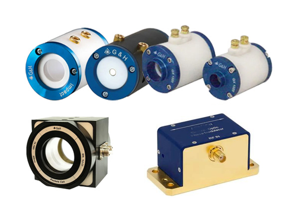
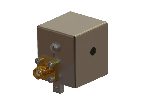
A new compressional mode, water-cooled, AO Q-Switch designed for use in high power unpolarised lasers giving faster switching, better pulse-to-pulse stability and higher power densities. Enhance your systems performance with greater punch and increased power, specifically for laser processing applications.
Before the Super Q-Switch, some customers were using 2 x Compressional mode Q-Switches (like the QS27-4C-S) in the same cavity. One of the Q-Switches is rotated 90degrees to the other. Because the Compressional mode Q-Switch is more efficient for polarised light, the first Q-Switch would block one polarisation & the second Q-Switch blocks the other. This is a good solution, but takes a large space in the cavity. The Super Q-Switch gives the same performance as using 2 x Compressional Q-Switch, but they are incorporated into 1 device.
This Q-switch uses a dual channel driver to operate two orthogonal compressional mode transducers bonded to a single monolithic optical cell and mounted in one convenient housing. Our proprietary bonding techniques and power handling technology allows this device to operate up to 50W per channel giving an efficient, compact, single device for the next generation of high power, high gain, solid state lasers.
| Part number | QS2x-xD-x-xxx | I-QS027-6.5D10G-B5 |
| Interaction Material | Fused Silica | Crystal Quartz |
| Wavelength | 1047 to 1064nm | 1047 to 1064nm |
| Anti-Reflection Coating | < 0.2% per surface | < 0 ·2% per surface |
| Damage Threshold | > 500MWcm-2 (1GWcm-2 typical) | 1064nm > 1GW/cm2 |
| Transmission (single pass) | > 99.6% | > 99 ·6% |
| Frequency | 24.00 or 27.12MHz | 27.12MHz |
| VSWR | < 1.2:1 (50. input impedance) | < 1.3:1 at 0dBm |
| Active Aperture | 1.6, 2, 3, 4, 5 or 6.5mm2 | 6.5mm |
| Clear Aperture | 9 x 9mm | 9 x 9mm |
| Acoustic Mode | Compressional (Orthogonal) | Compressional, dual |
| Rise-Time / Fall-Time | 109ns/mm | 113ns/mm |
| RF Power Rating | 2 x 50W CW | 50W per channel |
| Water Flow Rate | 190cc / minute, minimum | Water |
| Maximum Water Temperature | +40 deg;C (recommended, 22 deg;C to 32 deg;C) | 65ºC ± 5% |
| Water Connectors | Screw-fit or Barbed (push-on) | Barbed |
| Thermal Switch Cut-Off | +55 deg;C ± 5 deg;C | -20ºC to +70ºC |
| Housing / Flow Chamber Material | Aluminium HE30TF | Aluminium |
N390xx-yyDMzzz-2CH
Aperture size 1.6D, 2D or 3D, use 25W dual channel driver
Aperture size 4D, 5D or 6.5D, use 50W dual channel driver
The following table shows the RF powers required at the theoretical peak loss modulations for FS (Fused Silica) and CQ (Crystal Quartz) SQS (24/27MHz) and VHE devices (68MHz).
| Aperture size / mm | Approximate f / mm | FS SQS / W | CQ SQS / W | FS VHE / W | CQ VHE / W |
| 1.6 | 1 | ~15 | ~10 | ~55 | ~40 |
| 2 | 1.5 | ~20 | ~15 | ~70 | ~50 |
| 3 | 2 | ~25 | ~20 | ~100 (max) | ~70 |
| 4 | 2.5 | ~35 | ~25 | - | ~90 |
| 5 | 3.5 | ~45 | ~30 | - | ~100 (max) |
| 6.5 | 5 | ~50 (max) | ~40 | - | - |
All values are for 1064nm, SQS (super Q-switch) values stated are per channel.
STBR series Acousto-Optic Q-switching systems for industrial and laboratory applications. The STBR free space Q-switches are designed for the highest conversion efficiency of RF energy into acoustic energy by attaching the transducer to the crystal with an advanced vacuum metallized process. Q-switches are special modulators designed for use inside laser cavities. They are fabricated from high optical quality Fused Quartz, Flint Glass, and Tellurium Dioxide, or other acousto-optic materials with Brewster cut optical faces or durable hard oxide AR coatings for high optical power applications.
| Model # | FSQ-24-2-BC | FSQ-27-5-BC | FSQ-80-5-BC | TEQ-27-4-BC | TEQ-80-20-BC |
| Substrate | SiO2 | SiO2 | SiO2 | TeO2 | TeO2 |
| Brewster cut | yes | yes | ye | yes | yes |
| Laser Wavelength (nm) | 1064 | 1064 | 1060 | 2940 | 800 |
| Active Aperture (mm) | 2 | 2 | 1 | 1.5 | 3 |
| Center Frequency (MHz) | 2 | 27 | 80 | 27 | 80 |
| Digital Modulation Bandwidth (MHz) | 2 | 5 | 6.5 | 4 (3dB Bandwidth) | 20 (3dB Bandwidth) |
| Optical Transmission (%) | 99.8 | 99.8 | >99.5 | >99.5 | >99.5 |
| Maximum Diffraction Efficiency (%) | 30 | 30 | 25 | >50 | >65 |
| Rise Time (nsec) | 100 | 100 | 85 | 150/630 | 80/400 |
| Acoustic Velocity (m/s) | 5.96E+3 | 5.96E+3 | 5.96E+3 | 4.2E+3 | 4.2E+3 |
| Wave Front Distortion | lambda;/10 | lambda;/10 | lambda;/10 | lambda;/10 | lambda;/10 |
| Separation Angle | 5 mrad @ 1064nm | 5 mrad @ 1064nm | 5 mrad @ 1064nm | 1 deg @ 2940nm | 0.9 deg @ 800nm |
| Input Impedance | 50 ohms | 50 ohms | 50 ohms | 50 ohms | 50 ohms |
| Optical Polarization | Linear (perpendicular to acoustic wave) | Linear | Perpendicular to acoustic wave | ||
| VSWR | 2.1:1 | ||||
1. Which parameters do I need to specify if I want to order a Q-Switch?
You will need to specify the frequency, aperture, acoustic mode and the type of water connector.
2. Which frequency should I use?
The answer depends on your location. There are various regulatory bodies (for example the ITU) that stipulate the maximum levels of RF radiation that can be emitted in certain frequency bands. The Q-Switch drive frequency is usually chosen to be within one of the permitted bands for the country in which it will operate. Historically, 24.0MHz has been the chosen frequency in the USA and Japan and 27.12MHz in Europe and elsewhere. However, this has been less rigidly observed in recent years and 27.12MHz is now used widely in the USA.
3. What is the difference between clear aperture and active aperture? ,
The clear aperture of a Q-Switch is defined by the size of the block of silica in which the light and sound interact. For the QS24/27 Series the minimum clear aperture is 9mm.
The active aperture is defined by the height of the acoustic beam inside the silica block. This is the dimension that matters when specifying a Q-Switch.
4. How do I select the appropriate aperture for my application?
As a rule of thumb, the active aperture of the Q-Switch should be the same as the beam diameter of the laser at the point where the Q-Switch will be located. If the gain of the laser is modest it may be possible to use a Q-Switch with an active aperture one size smaller than the actual beam diameter (e.g. a 3mm active aperture Q-Switch in a laser with a 4mm diameter rod). This has the advantage of requiring lower RF drive power (drive power scales linearly with active aperture), which means less heat input and consequently greater efficiency and improved beam quality. It may even mean a lower cost driver can be used. On the downside, alignment of the Q-Switch in the cavity may be more critical.
5. Which acoustic mode would suit me best?
The choice is between shear (S) mode and compressional (C) mode (also known as longitudinal mode). If your laser is unpolarised you should choose shear mode. For polarised systems better results (less RF power = lower cost driver, less heat = better beam quality) will be obtained by using a compressional mode Q-Switch.
6. Which water connector should I choose?
The choice is between screw-on (S) connectors with a nut and olives which grip the outside of the flexible tubing, and barbed (B) push-on connectors, which grip the inside of the flexible tubing. There is little to choose between the two and it usually depends what type of pipe fitting is used as standard in the laser system. Overall the push-on fittings are probably best because there is no danger of them restricting the water flow. (The olives in the screw-on type can constrict the soft-wall tubing usually used in laser systems.)
7. How do I know that the Q-Switch is not over-heating?
The Q-Switch is fitted with a thermal interlock. If, for example, the cooling water fails it will shut down the driver when the temperature reaches 50 degrees C, preventing damage to the Q-Switch.
8. What is the optimum operating temperature of the Q-Switch?
The temperature should be set slightly above ambient to prevent the possibility of condensation forming on the optical surfaces of the Q-Switch. Around 32 degrees C is typical. For optimum performance and lifetime we do not recommend operating the Q-Switch at temperatures above 40 degrees C.
9. How do I know that the QS24/27 Series Q-Switch is the best choice for my application?
Please call one of our engineers if you are in any doubt about which Q-Switch to use. The QS24/27 Series Q-Switches are #39;industry standard #39; devices that have been developed and refined over many years. As a result they are very reliable and because they are manufactured in large quantities they are lower cost than some of the more specialised products we can offer. Basically, if you have a lamp-pumped industrial or medical Nd:YAG laser this is probably the Q-Switch for you. It is also suitable for the latest generation of high-power industrial diode-pumped lasers.
10. I am designing a compact laser and the QS24/27 Series Q-Switch is too large. What should I do?
We manufacture a range of standard compact Q-Switches that may be suitable for your application. If not, we have considerable experience of designing application-specific Q-Switches. We supply Q-switches to many of the leading diode-pumped laser manufacturers and it is likely that we will have a design that can easily be adapted to suit your requirements.
11. I have a single-mode polarised laser. Will the QS24/27 Series Q-Switch be suitable? ,
Yes. You can use a compressional mode version with a small active aperture (3mm or less). However, you may find that the integrated Q-switch, with its integral RF driver is a more cost effective solution that also offers performance advantages in terms of higher average Q-Switched output power.
12. How much laser power can I hold off? ,
It depends on the design of your laser cavity, where the Q-Switch is placed in it and so on. Hold-off is not a parameter of the Q-Switch alone, but of the Q-Switch/laser combination. We can however determine the extra-cavity loss modulation of the Q-Switch, which is a direct measure of its effectiveness at blocking the laser beam.
13. I have a high gain laser and need the maximum possible loss modulation. How do I achieve this? ,
There are two ways; by using two compressional mode Q-Switches in series and orientated such that the acoustic beams are orthogonal to each other you can obtain a high, polarisation insensitive, loss modulation with minimum RF drive power. Also available is a newly developed Q-Switch incorporating two orthogonal compressional mode transducers in a single monolithic cell and mounted in one convenient housing. A dual channel RF driver is available for both applications.
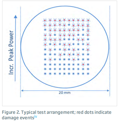
14. Can I trust the damage threshold quoted in the data sheet?
Yes. We periodically send a sample Q-Switch to a NIST certified test house to have the optical damage threshold verified. We take the utmost care in the polishing of the optical surfaces and in their preparation and coating. All these operations are carried out in-house in order to have total control of the process.
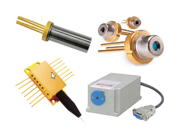
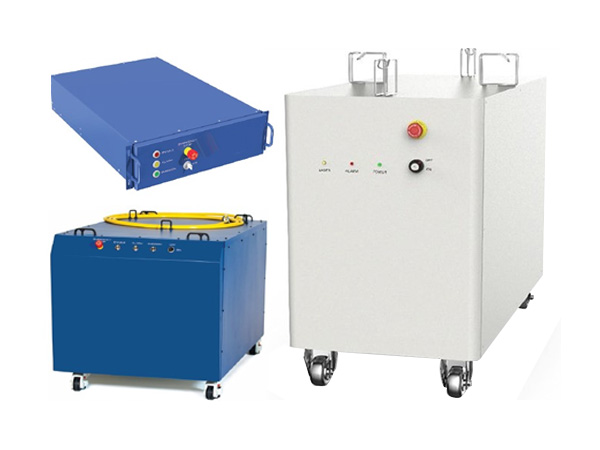
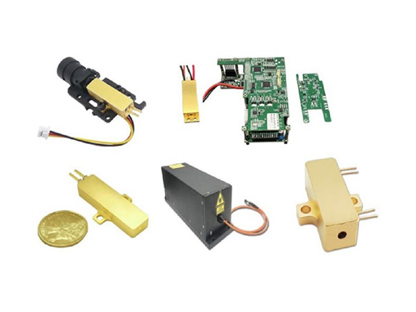
A leading supplier and manufacturer of a wide range of photonics products such as lasers,laser parts & machines.
Office: 10 Bukit Batok Crescent #07-02 The Spire Singapore 658079
Tel: +65 63167112
Fax: +65 63167113
Whatsapp: +65 91904616