 English
 Français
 Deutsch
 euskara
 Русский язык
 Italiano
 Português
 Nederlands
 Polski
 Greek
Greek Lietuva
 Türkçe
 日本語
日本語 한어
한어 中文
中文 தாமில்
 فارسی
فارسی हिंदी
हिंदी Tiếng Việt
 ภาษาไทย
 Pilipino
 Indonesia
 தாமில்
Send us a message
CLOSE


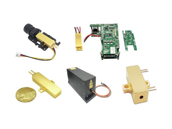


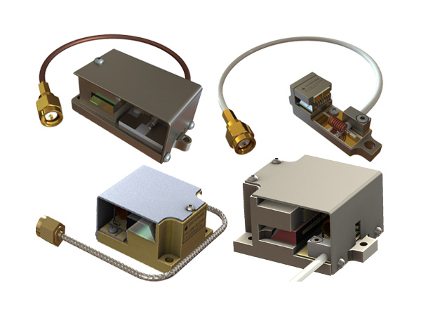
1.Free-Space High-Speed Modulators (Pockels Cell)
Our electro-optic modulators are based on a special crystal that has less piezo-effect and low charge migration than the traditional Mg-doped lithium niobate crystals, resulting in clean response with less ringing, more efficient with less power consumption, the ability to work at shorter wavelength and higher optical power. We produce two versions: resonant and direct driving. Both modify the phase, polarization or amplitude of a free-space laser: The resonant modulator drastically reduces driving voltage so that it can be driven by a laboratory function generator. Each device uniquely has three fixed resonance frequencies of 1MHz, 15MHz, and 30MHz that can be manually selected via a toggle switch. Our resonance electro-optic modulator is a cost effective and convenient device for testing applications. Custom frequencies up to 100MHz are also available. Another version is direct driving modulator that can be operated from DC to high frequencies. However, it needs a high voltage driver which determines its performance. We produce a high-voltage driver. Customers can use drivers from other manufacturers.
Applications
3mm aperture
Wide operation wavelength 450 to 1,550nm
High optical power handling
Low driving voltage ~12V (resonance)
One device with three frequencies to select (1, 15, 30MHz)
High repetition rate up to 100MHz (Resonance)
Broadband DC to 1MHz (non-Resonance)
Fiber coupled available
Customization available
1.1 Free-Space EOM (Pockels Cell)
(Phase or amplitude 3mm aperture, 300nm to 2000nm, DC-MHz)
The SAG-FEOM series free-space electro-optic Modulator uses a compensated electro-optic crystal pair — engineered for superior high-power handling and short-wavelength stability compared to conventional LiNbO₃ — to modulate the phase or amplitude of free-space laser beams across a broad wavelength range. Offered in single-pair and dual-pair crystal lengths to reduce drive voltage and enable deeper or faster modulation, the system operates from DC to MHz when paired with its matched driver. Optional accessories include polarization cubes for high-extinction-ratio amplitude modulation, isolators to prevent back-reflections, and an output detector for feedback control, with a polarized input beam required for amplitude-modulation operation.

Features:
High performance
Compact package
Easy integration
Customize available
Low cost
Applications:
Laser modulation
Holography
Metal cutting/engraving
Microfabrication
Specifications:
| Parameter | Specification (Unit) |
| Wavelength | 400~600nm |
| 600~900nm | |
| 900~1250nm | |
| 1250~1650nm | |
| Clear aperture | 3mm (Min) |
| Halfwave voltage, non-resonant | 80~600 V |
| Extinction ratio [1] | 10~30dB (Typical: 20 dB) |
| Input impedance, resonant | 50 ohms (Typical) |
| Input capacitance, non-resonant | 14pF (Typical) |
| Max optical power density | 532nm: 2~10 W [2] 1064nm: 5~20 W [2] |
| Temperature | -20~50°C |
Notes:
[1]: Related to the polarizer and beam quality
[2]: High power version available
Ordering Information:
| Series | Modulation type | Wavelength | Optical power | Crystal length | Input cube ** | Output cube ** | Driver | Isolator |
| SAG-FEOM | Amplitude=A Phase=P | 400~600nm = 05 600~900nm = 07 900~1250nm = 09 1250~1650nm = 14 320~500nm = 03 1920-2400nm = 20 | Regular=1 High Power=2 | 1x/2x/3x | No=1 Polacore =3 PBS=4 Glan-Thompson =5 | No=1 Polacore=3 PBS=4 Glan-Thompson=5 | Non=1 Yes=2 | None=1 One Stage =2 Two Stage =3 |
** Polacore: CW 10W/cm², PBS: CW 15W/cm², Glan-Thompson: CW 2kW/cm².
1.2 Resonant Free-Space EOM (Pockels Cell)
(2mm aperture, 400nm to 2000nm, fixed frequency from 1 to 100MHz)
The FEOM free-space electro-optic modulator is a crystal-based resonant modulator engineered to operate at a fixed resonance frequency, allowing low-voltage drive for phase, polarization, or amplitude modulation of a laser. Resonance frequencies are selectable from 5 to 20MHz. We offer both a standard version and a high-power version using RTP crystals to accommodate different application requirements. The standard unit uses a single crystal pair, while wavelengths above 1000nm require two pairs to achieve full modulation depth. The design minimizes piezo-electric effects and charge buildup, producing the characteristic sinusoidal response of resonance-driven devices. For amplitude modulation, polarized input light is required because the modulation process depends on controlling intensity through the polarization state. With input and output polarizers, the device achieves a significantly enhanced extinction ratio (ER).
Features:
Low loss
Ease to use
Low cost
Applications:
Laser Modulation
Specifications
| Parameter | Specification |
| Wavelength range | 400-600nm/600-900nm/900-1250nm/1250-1650nm |
| Halfwave voltage (non-resonant) | 225V @ 633nm |
| Halfwave voltage [1], resonant | 15V @ 633nm |
| Extinction ratio [2] | 10dB (Min) |
| Input impedance, resonant | 50ohms |
| Input capacitance @ non-resonance | 14pF |
| Aperture | 3mm (Max) |
| Max optical power density [3] | Standard: 2-4W/mm²; High Power: 1-500MW/mm² |
| Temperature | 20~50°C |
Notes:
[1]. Maximum modulation depth or phase shift voltage. The halfwave voltage increases as the wavelength increases.
[2]. Characterized at 633nm.
[3]. Wavelength dependent, typical is for 550nm, max is for 1060nm.
Resonant Modulator Half-Wave Voltage

Ordering Information:
| Series | Modulation type | Wavelength | Optical power | Resonant frequency | Input polarizer * | Output polarizer * | Isolator |
| SAG-REOM | Amplitude=A Phase=P | 250~400nm=03 400~600nm=05 600~900nm=07 900~1250nm=10 1250~1650nm=14 | Regular=1 2W=2 5W=5 10W=10 20W=20 50W=50 100W=100 300W=300 | 20MHz=20 5MHz=5 10MHz=10 30MHz=30 50MHz=50 | No=1 PBS=4 Glan-Thompson=5 | No=1 PBS=4 Glan-Thompson=5 | Single resonant Frequency version = F1 |
* PBS: CW 15W/cm² , Glan-Thompson: CW 2kW/cm².

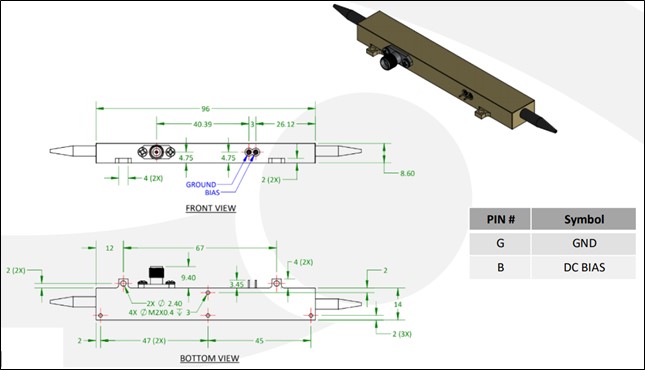
Mechanical Drawing (mm)

Modulator Half-Wave Voltage

Operation Instructions
1. Input a lignment- Direct the laser beam through the device, ensuring proper alignment along the optical axis without hitting the crystal walls.
2. Input olarizer setup- Place a vertical polarizer at the input side. Adjust the input laser polarization direction to achieve maximum output intensity.
3. Output polarizer setup- Place a horizontal polarizer at the output side of the device. Carefully adjust the orientation of the output polarizer to achieve minimum transmitted output intensity (extinction condition).
4. Apply Control Voltage- Gradually apply voltage to the device and observe changes in the output intensity. At the operating voltage (Vp), the output intensity will reach its maximum.
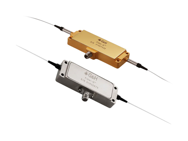
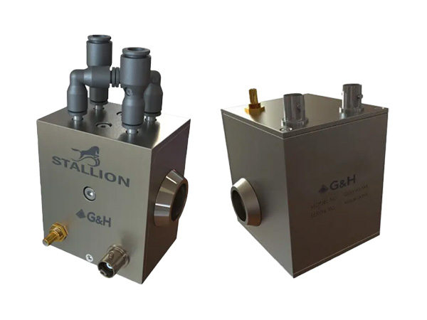
1.3GHz Resonant Optical Phase Modulator (1-3.05GHz, temperature control option)
The GHz resonant optical phase modulator delivers high-speed optical phase modulation using advanced electro-optical technology. It features an integrated resonance electrical circuit within the package, enabling operation with a low driving voltage. Packaging options include free-space and fiber-coupled configurations, with additional choices for TEC temperature stabilization and integration with an amplifier driver to increase modulation depth. The operation requires linearly polarized light.
Features
High speed
Ultra-high reliability
Low insertion loss
Compact
Applications
Atomic clock
Optical blocking
Configurable operation
Instrumentation
Specifications
| Parameter | Specification |
| Resonance frequency | 0.7~3.05GHz |
| Bandwidth | 3.8~10MHz |
| Q factor | 325 |
| Wavefront distortion @633nm | Max: 1/6λ |
| Modulation depth | Max: 2.5rad |
| Sensitivity | 0.38~0.47rad/V |
| Required RF power (1 rad @400nm) | 35dBm |
| Input impedance | 50Ω |
| RF connector | SMA-F |
| Max RF power | 5W |
| Optical aperture | 1~2mm² |
| Max optical power | 1W/mm² |
| Optical wavelength | 350~780nm |
| Operating temperature [1] | 5°C |
| Storage temperature | -40~85°C |
Note
[1] TEC actively cooled
Ordering Information:
| Series | Type | Wavelength | Resonance Frequency | Input Fiber | TEC | RF Amplifier |
| SAG-GHZM | Standard=11 Special=00 | 532=5 780=7 650=6 550=5 450=4 350=3 Special=0 | 1.12GHz=112 3.05GHz= 305 1.75GHz= 175 | Non=1 PM480=4 Special=0 | Non=1 Yes=2 | Non =1 Yes=2 |
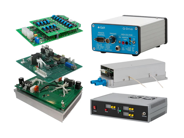
2. High Voltage EO Driver (up to 400V)
The HVED series analog high voltage drivers provide up to ±200V with 1MHz bandwidth or 400V with 0.5MHz bandwidth, ideal for driving non-resonant EO phase modulators to modulate optical signals at wavelengths up to 1060nm. A polarity modulation feature minimizes charge buildup from photorefractive effects, particularly at shorter wavelengths and higher power.
The drivers include an adjustable DC bias up to 50V for precise performance tuning. For example, with a sweep range of -200V to +200V and a 10V DC bias, the output shifts to -190V to +210V (clipping the positive side), while a 100V DC bias adjusts to -100V to +100V. This bias flexibility allows precise control, optimizing electro-optic device functionality.
For amplitude modulation, polarized light is essential because the modulation process relies on controlling the intensity of light based on its polarization state. By incorporating input and output polarizers, the extinction ratio (ER) of the device is significantly improved.

Features
400V high voltage
10ns rise/fall
Analog response
Applications
EO Device Control
Specifications
| Parameter | Specification |
| Output voltage | 0~400V (Typical: ±220V) |
| Rise/fall time [1] | 7~10ns (Typical: 7ns) |
| Bias voltage | 0~50V |
| Delay time | Max: 200ns |
| Repetition rate | 0.5~0.7MHz (Typical: 0.5MHz) |
| Pulse jitter | 1~20ps |
| Operating temperature | -5~40°C |
| Power input | 100~240ACV |
| Power consumption | Max: 10W |
| Control input | 0~5V |
| Humidity 90% | Noncondensing |
| Storage temperature | -40~85°C |
Notes
1. At 10-90% level. Also affected by amplitude and capacitor load. For 400V output, repetition rate is 0.5MHz
Ordering Information:
| Series | Max voltage | Package | Configuration | Repetition * |
| SAG-HVED | ±220V=22 400V=40 Special=00 | Benchtop=1 PCB=2 Special=0 | Standard=1 Special=0 | 0.3MHz=1 0.5MHz=2 0.7MHz=3 |
* 1MHz only available for 220V version.
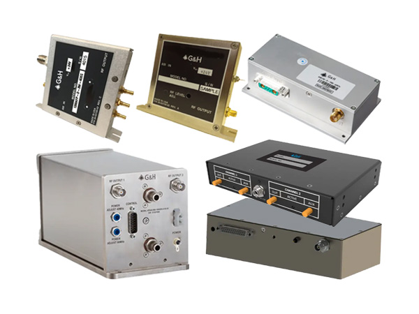
List of EO Modulators & Drivers
Phase Modulator
Intensity Modulator
Driver
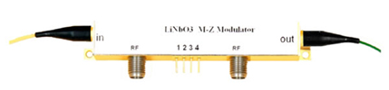
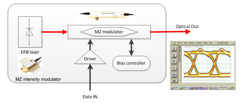
The STK-AM series electro-optic intensity modulator utilizes the electro-optical effect of lithium niobate and push-pull Mach-Zehnder interference structure to achieve intensity modulation of optical signals. It features low insertion loss, high modulation bandwidth, high extinction ratio, low half-wave voltage and high damage optical power. This product is mainly used for electro-optical signal conversion in high-speed optical fiber communication systems, the generation of light sidebands, high extinction ratio light pulse generation in quantum communication, microwave fiber link and other fields.
Wavelengths optional
Low half-wave voltage
High bandwidth
Low insertion loss
High-speed optical fiber communication systems
Microwave fiber link
Quantum communication
| Parameters | Symbol | STK-AM-08 | STK-AM-10 | STK-AM-15-10G | STK-AM-15-20G |
| Wavelength | 830±40 | 1064±60 | 1550±100nm | 155±100nm | |
| Insertion loss | IL | <5 dB | <4 dB | <4 dB | <4.5 dB |
| Optical return loss | ORL | -40 dB | -45 dB | -45dB | -45dB |
| Bandwidth (-3dB) | S21 | 2.5GHz | 10GHz- | 10GHz | 20GHz |
| Rise time 10%~90% | tr | 150ps | 35ps | 35ps | 18ps |
| Half-wave voltage @50KHz, RF | Vπ | 5V | 4.5V | 4V | 5V |
| Half wave voltage @Bias | Vπ | 6V | 6V | 5V | 5V |
| Extinction ratio | ER | 28dB | 30dB | >25dB | >25dB |
| Input resistance | ZRF | 50 @RF, 1M @Bias | |||
| Electrical interface | SMA(f) | K(f) | |||
| Electrical return loss | S11 | <-10dB | |||
| Input fiber | PM Panda slow axis alignment | ||||
| Output fiber | Single mode fiber or PM fiber | ||||
| Fiber connector | FC/APC or customer specified | ||||
| Operating temperature | Top | -10~60C | |||
| Storage temperature | Tst | -40~80C | |||
| RF input power | Pi | <28dBm | |||
| Max. input optical power | Po | 30mW | 50mW | 100mW | 100mW |
1064nm Operation
Low insertion loss
3dB bandwidth 5GHz
Low half-wave voltage
High Extinction Ratio >50dB
Optical Pulse Generation
Optical fiber sensing system
Laser mode locking
The 1064nm high extinction ratio electro-optical intensity modulator integrates two Mach-Zehnder intensity modulators with a push-pull structure, which can achieve an extinction ratio of up to 50dB. It is used in the fields of high-speed optical pulse generation, fiber sensing, and laser mode locking.
| Parameters | Symbol | Min. | Typ. | Max. | Unit | ||
| Optical Parameters | |||||||
| Cystal | LiNbO3 X-Cut Y-Prop | ||||||
| Waveguide process | APE | ||||||
| Wavelength | 980 | 1064 | 1100 | nm | |||
| Insertion loss* | IL | 7 | 8 | dB | |||
| Optical return loss | ORL | -40 | dB | ||||
| Extinction ratio @DC | ER@DC | 50 | dB | ||||
| Polarization extinction ratio* | PER | 25 | 28 | dB | |||
| Fiber | Input | Panda PM 980 | |||||
| Output | Panda PM 980 | ||||||
| Fiber connector | FC/PC、FC/APC or user specified | ||||||
| Electrical Parameters | |||||||
| Bandwidth(-3dB) | S21 | 5 | GHz | ||||
| Half-wave voltage Vpi | RF1 & RF2 | Vπ@50KHz | 4.5 | 5 | V | ||
| Bias1 & Bias2 | Vπ@Bias | 4 | 5 | V | |||
| Electrical return loss | S11 | -12 | -10 | dB | |||
| Input impedance | RF1 & RF2 | ZRF | 50 | ||||
| Bias1 & Bias2 | ZBIAS | 1M | |||||
| Electrical connector | RF1 & RF2 | SMA(f) | |||||
| Bias1 & Bias2 | 4pin | ||||||
*with connector
| Parameters | Symbol | Unit | Min. | Typ. | Max. |
| Input optical power | Pin,Max | dBm | 10 | ||
| RF input power | dBm | 28 | |||
| Bias voltage | Vbias | V | -15 | 15 | |
| Operating temperature | Top | ºC | -10 | 60 | |
| Storage temperature | Tst | ºC | -40 | 85 | |
| Humidity | RH | % | 5 | 90 | |
| Dimension | mm | 111x12.5x9 |
STK-AM-10-BW-PP-FA/FP-HER
WL—Wavelength: 10-1064nm
BW—Bandwidth: 5G---5GHz
FA/FP—Connector: FA---FC/APC; FP---FC/PC

Key Features
C and L-Band Operation
Low insertion loss
3dB bandwidth 10GHz
Extinction ratio 35/40dB
Low half-wave voltage
Integrated Monitor Photodiode
Telecordia GR-468-CORE
Microwave fiber link
Quantum communication
Optical pulse generation
Optical fiber sensing system
Laser mode locking
The 1550nm High Extinction Ratio LiNbO3 electro-optical intensity modulator based on the M-Z push-pull structure has a low half-wave voltage and stable physical and chemical characteristics, and the device has a high response rate, high extinction ratio(>40dB) and is therefore widely used in microwave fiber link, Quantum communication, optical Q-switched systems, laser mode-locking, and fiber sensing .
| Parameters | Symbol | Min. | Typ. | Max. | Unit | |
| Optical Parameters | ||||||
| Wavelength | 1525 | 1565 | nm | |||
| Insertion loss(with connector) | IL | 4 | 5 | dB | ||
| Optical return loss | ORL | -45 | dB | |||
| Extinction ratio @DC | ER@DC | 35 | 40 | dB | ||
| Fiber | Input | Panda PM Fujikura SM 15-P-8/125-UV/UV-400 | ||||
| Output | Panda PM Fujikura SM 15-P-8/125-UV/UV-400 | |||||
| Fiber interface | FC/PC、FC/APC or user specified | |||||
| Electrical Parameters | ||||||
| Bandwidth(-3dB) | S21 | 10 | 12 | GHz | ||
| Rise time (10%~90%) | Tr | 35 | ps | |||
| Half-wave voltage Vpi | RF | Vπ@50KHz | 5 | V | ||
| Bias | Vπ@Bias | 6 | V | |||
| Electrical return loss | S11 | -12 | -10 | dB | ||
| Photodiode Responsivity | RP | 10-3 | A/W | |||
| Input impedance | RF | ZRF | 50 | |||
| Bias | ZBIAS | 1M | ||||
| Electrical interface | SMA(f) | |||||
| Dimension | 111x12.5x9 | mm | ||||
| Parameters | Symbol | Unit | Min. | Typ. | Max. |
| Input optical power | Pin,Max | dBm | 20 | ||
| RF input power | dBm | 28 | |||
| Bias voltage | Vbias | V | -20 | 20 | |
| Operating temperature | Top | ºC | -10 | 60 | |
| Storage temperature | Tst | ºC | -40 | 85 | |
| Humidity | RH | % | 5 | 90 |

WL—Wavelength:15-1550nm
BW—Bandwidth:10G---10GHz 20G-20GHz
FA/FP—Connector:FA---FC/APC; FP---FC/PC
ER----Extinction Ratio: 35dB, 40dB
We can provide with the driver for the above electro-modulators and integrate the modulator, amplifier and relevant controllers together. The user can manually or automatically set the bias points. At the manual setting mode, the bias can be displayed and the EO modulator and amplifier individually operate. At the automatic setting mode, the user can set various bias points according to the demand and the bias point is locked and displayed. The modulation performance of the modulator is not influenced by external factors such as environment temperature and vibration.
| Symbol | Min | Typical | Max | Unit | ||
| Optical parameters | ||||||
| Wavelength | l | 1520 | 1550 | 1610 | nm | |
| Crystal | LiNbO3 | |||||
| Insertion loss | @Peak | IL | 4.5 | 5.5 | dB | |
| @Q | IL | 7 | 8 | dB | ||
| Optical return loss | ORL | -45 | dB | |||
| Extinction ratio @DC | ER@DC | 25 | 28 | dB | ||
| Fiber | Input | Panda PM Fujikura SM 15-P-8/125-UV/UV-400 | ||||
| Output | Corning SMF-28 | |||||
| Electrical parameters | ||||||
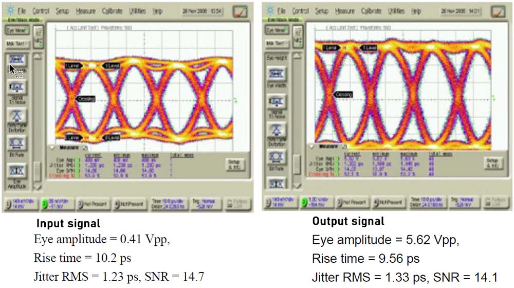
| Bandwidth (-3dB) | S21 | 10 | 12 | GHz | ||
| Working speed | 10K | 12.5G | bps | |||
| Input signal format | NRZ | |||||
| Input signal amplitude | Vi | 0.25 | 0.4 | 0.8 | Vpp | |
| Half-wave voltage @10Gbps | Vπ | 4.5 | 5.0 | V | ||
| Dynamic extinction ratio@10Gbps NRZ | DER | 12 | dB | |||
| Rise time (10%-90%) | Tr | 30 | 35 | ps | ||
| Additional vibration* | JitterRMS | 1.1 | 1.7 | 2.0 | ps | |
| Amplification gain | G | 0 | 25 | dB | ||
| Loss from waves | S11 | -12 | -10 | dB | ||
| Input impedance @RF input | ZRF | 50 | W | |||
| Manual setting mode | ||||||
| Bias voltage | Vbias | -10 | 10 | V | ||
| Adj. accuracy | 0.1 | V | ||||
| Automatic setting mode | ||||||
| Bias | Null, Q+/-, Peak | |||||
| Vibration period | F | 1 | KHz | |||
| Vibration amplitude | Vpp | 2%Vπ | ||||
| Harmonic extinction ratio | 40 | 50 | dB | |||
| Optical power stability | DP | 0.1 | dB | |||
| Duty | 45 | 55 | % | |||
| Other parameters | ||||||
| Input interface | SMA(f) | |||||
| Optical interface | Input | FC/APC PM | ||||
| Output | FC/APC SM | |||||
| Input power | VDC | AC 220 | V | |||
| Dimension | LxWxH | 270x300x90 | mm | |||
| Weight | <5 | kg | ||||
| Port | RS232 | |||||
| Display contents | Manual | Amplification gain, real-time bias voltage | ||||
| Automatic | Amplification gain, bias Vpi, real-time bias voltage, bias lock status | |||||
Ordering Information: STK-MU-W-XX-BW-FB-YY-M/A
W: wavelength such as 15-1550nm, 13-1310nm, 10-1064nm
XX: modulation method such as NRZ, DPSK, DQPSK, DPQPSK, AN, PM
BW: bandwidth such as 02-2.5G, 10-10G, 20-20G, 40-40G
FB: input/output fiber type such as PP (input & output are PM), PS (input is PM and output is SM)
YY: fiber connector such as FA-FC/APC, FP-FC/PC
M/A: control mode, M is manual and A is automatic.
The STK-KY-PM series electro-optic phase modulator utilizes the electro-optical effect of lithium niobate to achieve phase modulation of optical signals, and uses titanium diffusion or proton exchange process to fabricate optical waveguides, which can achieve dual-polarization or single-polarization phase modulation. It has low insertion loss, high modulation bandwidth, low half-wave voltage, high damage optical power, etc. This product is mainly used for optical chirp control in high-speed optical communication systems, phase delay in coherent communication systems, the generation of optical sidebands, phase modulation in quantum communication, reducing stimulated Brillouin scattering (SBS) in analog optical fiber communication systems and other fields.
Wavelengths optional
Low half-wave voltage
Low insertion loss
High damage optical power
Optical fiber sensing systems
Optical fiber communication
Laser coherent synthesis
Phase delay (movement)
Quantum communication
| Parameters | Symbol | STK-PM830-1 | STK-PM1064-1 | STK-PM1550-1 | STK-PM1550-2 |
| Wavelength | 830+/-40 | 1064+/-60 | 1550+/-50nm | ||
| Insertion loss | IL | <5 dB | <4 dB | <4 dB | 4 dB |
| Optical return loss | ORL | -40 dB | -45 dB | -45dB | -40 dB |
| Bandwidth (-3dB) | S21 | 2.5GHz | 10GHz- | 300MHz | 10GHz |
| Rise time 10%~90% | tr | 150ps | 35ps | 1ns | 35ps |
| Vpi@50KHz | Vπ | 5V | 4.5V | 4V | 4V |
| Input resistance | ZRF | 50 | 1M | 50 | |
| Electrical interface | SMA(f) | 3pin | SMA(f) | ||
| Electrical return loss | S11 | <-10dB | |||
| Input/output fiber | PM Panda slow axis alignment | ||||
| Fiber connector | FC/APC or customer specified | ||||
| Operating temperature | Top | -10~60C | |||
| Storage temperature | Tst | -40~80C | |||
| RF input power | Pi | <28dBm | |||
| Maximum input optical power | Po | 30mW | 100mW | 100mW | 100mW |
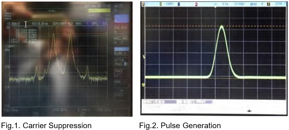
The STK-MU-SSB-15 series product is an optical CS-SSB modulation module developed by our company. The modulation module integrates Mach-Zehnder dual parallel modulators, bias point control circuits, 90 degree hybrid splitter, can achieve stable and reliable single sideband modulation, and can switch between left and right sideband control as needed. This product is mainly used in Brillouin fiber sensing systems, microwave photonics, gas detection and other fields.
Key Features
Wavelength C-band
Sideband suppression ratio:>30dB
Carrier suppression ratio: >26dB
Up and down sidebands
Convenient to use and reliable
Optical fiber sensing system
Microwave photonics
Gas detection
Optical fiber communication systems
| Parameters | Symbol | Min. | Typ. | Max. | Unit |
| Carrier Optical Source Parameters (Provided by the user) | |||||
| Laser type | DFB source or wavelength tunable source | ||||
| Wavelength | l | 1510 | 1560 | nm | |
| Line width | Dn | - | 1 | MHz | |
| Polarization extinction ratio | PER | 20 | - | dB | |
| Power | Pi | 10 | 100 | mW | |
| Modulator Specification Parameters | |||||
| Modulator type | X-cut double parallel M-Z modulator | ||||
| Modulator bandwidth S21@3dB | BW | 10 | 12 | - | GHz |
| Insertion loss | IL | 7 | 8 | dB | |
| Return loss | RL | -45 | -50 | - | dB |
| Bias Controller Parameters | |||||
| Automatic feedback bias controller | Jitter mode | ||||
| Jitter signal frequency | 400 | 1000 | 1400 | Hz | |
| Jitter signal amplitude | 10 | 50 | 1000 | mV | |
| Preset work point | Lowest point | ||||
| CS-SSB Optical Output Signal | |||||
| Single sideband modulation range* | F | 1 | 12 | GHz | |
| Input RF power | PRF | -5 | 5 | dBm | |
| Sideband suppression ratio @1550nm | 30 | 35 | - | dB | |
| Carrier suppression ratio @1550nm | 26 | 32 | dB | ||
| Interface | |||||
| Input fiber | Panda type polarization-maintaining fiber | ||||
| Output fiber | Panda type polarization-maintaining fiber | ||||
| Fiber optic interface | PM FC/APC Slow axis alignment | ||||
| Input RF signal interface | SMA(50Ω) | ||||
| Bias controller communication interface | J30J | ||||
| Other Parameters | |||||
| Operating temperature | To | +15 | - | +35 | ºC |
| Stored temperature | Ts | -40 | - | +75 | ºC |
| Power supply | V | - | 15 | - | V |
| Module size | LWH | 160*125*20 mm | |||
| Weight | - | 0.3 | - | Kg | |

Key Features
10G, 20G, 40GHz optional bandwidth
Gain> 25dB
Saturated output Max.25dBm (11Vpp)
Rise time Min.<8ps
Low jitter
DC12V power supply
Easy to use
High-speed optical fiber communication system
Quantum communication
Picosecond pulse amplification
Optical fiber sensing system
10G driver module
10G high output driver module
20G driver module
40G driver module
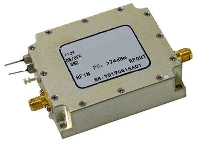
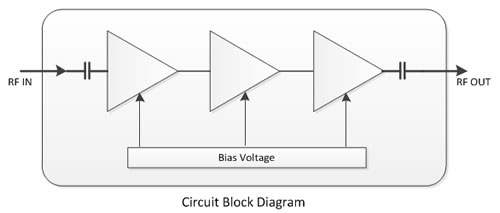
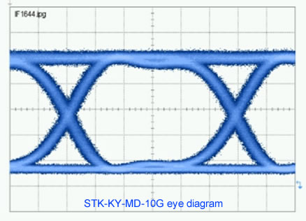
The STK-KY-MD-XX series electro-optic modulator driver is a broadband, high-output driver amplifier mainly used for lithium niobate electro-optical intensity and phase modulator. Its working bandwidth is up to 30K ~ 40GHz, and it can achieve a maximum of 42Gbps NRZ wideband signal amplification up to 8Vpp. It is mainly used in high-speed optical fiber communication systems, quantum communication, picosecond pulse amplification, and optical fiber sensing systems.
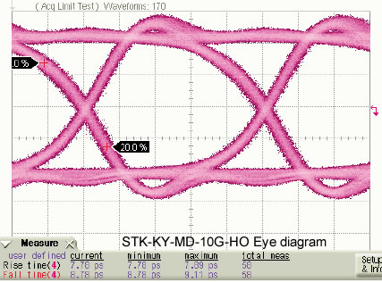
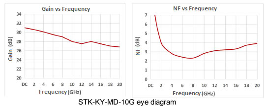
| Parameters | Symbol | Unit | STK-MD-10G | STK-MD-10G-HO | STK-MD-20G | STK-MD-40G | |
| Bandwidth(-3dB) | S21-High | GHz | >10 | >8 | >20 | >35 | |
| S21-Low | KHz | 30 | 100 | 30 | 30 | ||
| Data rate | bps | 100k~12.5G | 100k~10G | 100k~25G | 100k~42G | ||
| Gain | G | dB | >26 | >30 | >28 | >28 | |
| Gain ripple | DG | dB | <3 | <3 | <3 | <3 | |
| Output amplitude | Vout | Vpp | 8 | 11 | 8 | 8 | |
| Saturated output power | Ps | dBm | 23 | 25 | 23 | 23 | |
| Rise time (10% -90%) | Tr | ps | 35 | 40 | 18 | 8 | |
| Jitter | JitterRMS | ps | <2 | <2 | <1 | <1 | |
| Isolation | S12 | dB | <-40 | ||||
| Electrical return loss | S11 | dB | <-12 | <-10 | <-10 | <-10 | |
| RF connector | SMA(f) | K(f) | |||||
| Operating Voltage | VDC | V | DC 12V | ||||
| Working current | Io | mA | <500 | ||||
| Dimensions | LxWxH | mm | 50x33x15 | ||||
| Parameters | Symbol | Unit | Min. | Typ. | Max. |
| Input signal amplitude | Vin | Vpp | 1.5 | ||
| Operating Voltage | DC | V | 11.5 | 13 | |
| Operating temperature | Top | ºC | -20 | 60 | |
| Storage temperature | Tst | ºC | -40 | 85 |
STK-IQ-15-20G-PP-FA
Features:
Low insertion loss.
Low half-wave voltage
High extinction ratio
Built-in detector
Application:
Single Side Band modulation.
QPSK, QAM, OFDM modulation
FWCW LiDAR
Introduction
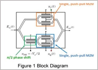
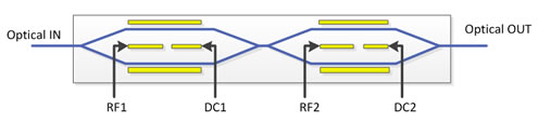
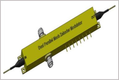
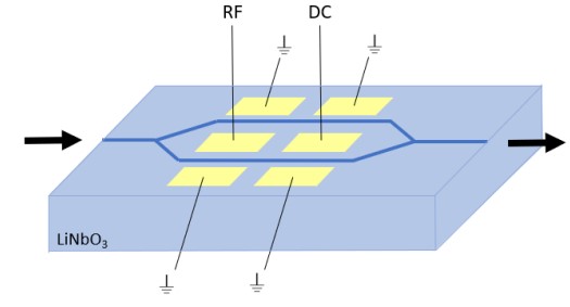
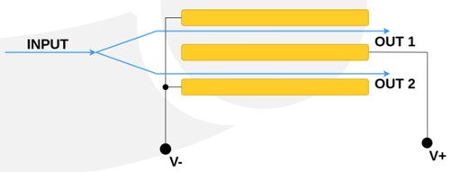
STK-IQ-15-20G-PP-FA is a wideband, low insertion loss dual parallel Mach Zehnder interference modulator, which is prepared by Titanium diffusion process, with high bandwidth and low driving voltage. The dual parallel IQ modulator integrates two sub-MZs and an external master MZ with essentially the same structure and performance, as shown in Figure 1. It contains two RF signal input ports of I and Q channels, and three bias voltage ports of MZ structure, which has a high integration, stable working performance, so can independently realize single-sideband modulation and QAM modulation methods such as carrier suppression.
The operating wavelength of the dual parallel IQ modulator is C+L band, 3dB bandwidth can up to 25GHz. It uses 2.92mm female connector, input and output are Panda type polarization maintaining fiber, and optical fiber connector can choose FC/APC or FC/PC. It has two built-in monitoring PDs and the corresponding bias point control circuit, to realize the modulator is not affected by the external environment and works stably for long time. It mainly used in QAM and other high-speed optical fiber communication and distributed optical fiber sensing and other fields. For the application environment, we can provide industrial grade -40~70 °C, military grade -55~70 °C and anti-irradiation aerospace grade products.
Parameters
| Parameters | Symbol | Min. | Typ. | Max. | Unit |
| Wavelength | λ | 1530 | 1550 | 1610 | nm |
| Crystal | Lithium Niobate X-Cut Y-Prop | ||||
| Insertion loss | IL | 5 | 6.5 | dB | |
| Extinction ratio @DC | ER | 20 | 23 | dB | |
| 3dB Bandwidth | BW | 20 | 25 | GHz | |
Electrical Return loss | S11 | -12 | -10 | dB | |
| DC half-wave voltage | VπDC1.2 | 6 | 7 | V | |
| VπDC3 | 7 | 8 | V | ||
RF half-wave voltage | VπRF@50KHz | 5 | 6 | V | |
| Impedance | ZRF | 50 | Ω | ||
| Optical Return loss | ORL | 40 | 45 | dB | |
| Polarization Extinction Ratio | PER | 20 | 23 | dB | |
Absolute Maximum Ratings
Parameters | Symbol | Unit | Min. | Typ. | Max. |
| RF input power | RPi | dBm | 27 | ||
| Optical input power | OPi | dBm | 20 | ||
| Bias voltage | Vb | V | -15 | 15 | |
| Operating temperature* | Top | ºC | -10 | 70 | |
| Storage temperature | Tst | ºC | -40 | 85 | |
| Humidity | RH | % | 5 | 90 |
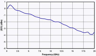
Typical Curve:
Dimension:
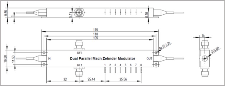
Pin definition | ||
PIN | Function | Note |
IN | Optical input | Panda PM fiber (slow axis), FC/APC |
OUT | Optical input | Panda PM fiber (slow axis) or SM fiber, FC/APC |
RF1,2 | RF1/2 input | 2.92 female K |
1 | Ground | GND |
2,3,4 | DC1, DC2, DC3 + | DC bias |
5,6 | PD1 -/+ | PD1 Cathode/Anode |
7,8 | PD2 -/+ | PD2 Cathode/Anode |
SCQ series electro-optic modulators have the features of low insertion loss, wide bandwidth, low half-wave voltage etc and are to be used in space optical communication, time base, pulse generator and quantum optics etc.
SCQ series electro-optic modulators are mainly divided into two groups: intensity modulators and phase modulators. Their working wavelengths are 780nm, 850nm, 1064nm, 1310nm, 1550nm and 2000nm。Other wavelengths are available upon request.
Definition of Part Numbers: SCQ-XX-WW-XG-F-FC
XX: modulator type. AM is intensity modulator and PM is phase modulator.
WW: operation wavelength, such as 850nm, 1064nm, 1310nm,1550nm and 2000nm
XG: operation bandwidth, such as 2.5G, 10G, 40G
F: In-out fiber such as PP (PM/PMF)
FC: fiber connector such as FA (FC/APC), FP (FC/PC)
| Part number | Operation wavelength nm | Min wavelength nm | Max wavelength nm | Bandwidth Hz | In/out fiber | Fiber connector |
| SCQ-AM-850-10G | 850 | 830 | 870 | 10G | PM/PM | FA, FP |
| SCQ-AM-1064-10G | 1060 | 980 | 1150 | 10G | PM/PM | FA, FP |
| SCQ-AM-1310-2.5G | 1310 | 1290 | 1330 | 2.5G | PM/PM | FA, FP |
| SCQ-AM-1550-2.5G | 1550 | 1530 | 1565 | 2.5G | PM/PM | FA, FP |
| SCQ-AM-1550-10G | 1550 | 1530 | 1565 | 10G | PM/PM | FA, FP |
| SCQ-AM-1550-20G | 1550 | 1530 | 1565 | 18G | PM/PM | FA, FP |
| SCQ-AM-1550-40G | 1550 | 1530 | 1565 | 28G | PM/PM | FA, FP |
1.1 SCQ-AM-1310 Series 1310nm Intensity Modulators
The LiNbO3 intensity modulator is widely used in high-speed optical communication system, laser sensing and ROF systems because of well electro-optic effect. The SCQ-AM series based on MZ structure and X-cut design, has stable physical and chemical characteristics, which can be applied both in laboratory experiments and industrial systems.
Features:
Low insertion loss
Bandwidth: 2.5GHz
Low half-wave voltage
Customization option
Applications:
ROF systems
Quantum key distribution
Laser sensing systems
Side-band modulation
Optical Parameters:
| Parameter | Symbol | Min | Typ | Max | Unit |
| Operating wavelength | | 1290 | 1310 | 1330 | nm |
| Insertion loss | IL | 4 | 5 | dB | |
| Optical return loss | ORL | -45 | dB | ||
| Switch extinction ratio @DC | ER@DC | 20 | 23 | dB | |
| Dynamic extinction ratio | DER | 13 | dB | ||
| Optical fiber (Input port) | PM Fiber (125/250μm) | ||||
| Optical fiber (Output port) | PM Fiber or SM Fiber (125/250μm) | ||||
| Optical fiber interface | FC/PC、FC/APC Or Customization | ||||
Electrical Parameters:
| Parameter | Symbol | Min | Typ | Max | Unit |
| Operating bandwidth (-3dB) | S21 | 2.5 | GHz | ||
| Half-wave voltage (RF) | VΠ@1KHz | 3 | 4 | V | |
| Half-wave voltage (Bias) | VΠ@1KHz | 3.5 | 4.5 | V | |
| Electrical return loss | S11 | -12 | -10 | dB | |
| Input impedance (RF) | ZRF | 50 | W | ||
| Input impedance (Bias) | ZBIAS | 1M | W | ||
| Electrical interface | SMA(f) | ||||
Limit Conditions:
| Parameter | Symbol | Unit | Min | Typ | Max |
| Input optical power | Pin, Max | dBm | 20 | ||
| Input RF power | dBm | 28 | |||
| ias voltage | Vbias | V | -15 | 15 | |
| Operating temperature | Top | ℃ | -10 | 60 | |
| Storage temperature | Tst | ℃ | -40 | 85 | |
| Humidity | RH | % | 5 | 90 |
Order Information:
| SCQ | AM | 13 | 2.5G | XX | XX |
| SCQ series | Type: AM---Intensity Modulator | Wavelength: 13---1310nm | Operation bandwidth: 2.5G---2.5GHz | In-Out Fiber type: PP---PM/PM | Optical connector: FA---FC/APC FP---FC/PC SP---Customization |
| PORT | Symbol | Note |
| In | Optical input port | PM Fiber (125μm/250μm) |
| Out | Optical output port | PM and SM Fiber option |
| RF | RF input port | SMA(f) |
| Bias | Bias control port | 1,2 Bias, 34-N/C |
| Part number | Operation wavelength nm | Min wavelength nm | Max wavelength nm | Bandwidth Hz | In/out fiber | Fiber connector |
| SCQ-PM-780-10G | 780 | 760 | 800 | 10G | PM/PM | FA, FP |
| SCQ-PM-850-10G | 850 | 780 | 890 | 10G | PM/PM | FA, FP |
| SCQ-PM-1064-300M | 1060 | 980 | 1150 | 300M | PM/PM | FA, FP |
| SCQ-PM-1064-10G | 1060 | 980 | 1150 | 10G | PM/PM | FA, FP |
| SCQ-PM-1310-10G | 1310 | 1290 | 1330 | 10G | PM/PM | FA, FP |
| SCQ-PM-1550-300M | 1550 | 1530 | 1565 | 300M | PM/PM | FA, FP |
| SCQ-PM-1550-10G | 1550 | 1530 | 1565 | 10G | PM/PM | FA, FP |
| SCQ-PM-1550-20G | 1550 | 1530 | 1565 | 20G | PM/PM | FA, FP |
2.1 SCQ-PM Series 1310nm Electro-optical Phase Modulators
The LiNbO3 phase modulator is widely used in a high-speed optical communication system, laser sensing, and ROF systems because of well electro-optic effect. The SCQ-PM-1310 series, based on Ti-diffused technology, has stable physical and chemical characteristics, which can meet most applications in laboratory experiments and industrial systems.
Features:
Low insertion loss
Polarization-maintaining
Low half-wave voltage
Dual-polarization option
Application:
Optical communication
Quantum key distribution
Frequency shifting
Optical parameters:
Parameter | Symbol | Min | Typ | Max | Unit | |
Operating wavelength | l | 1290 | 1310 | 1330 | nm | |
Insertion loss | IL | 3.5 | 4 | dB | ||
Optical return loss | ORL | -45 | dB | |||
Polarization extinction ratio | PER | 20 | dB | |||
| Optical fiber | Input port | PM fiber(125/250μm) | ||||
| Output port | PM fiber(125/250μm) | |||||
Optical fiber interface | FC/PC、FC/APC Or Customization | |||||
Electrical Parameters:
| Parameter | Symbol | Min | Typ | Max | Unit |
| Operating bandwidth(-3dB) | S21 | 10 | 12 | GHz | |
| Half-wave voltage @50KHz | VΠ | 2.7 | 3 | V | |
| Electrical return loss | S11 | -12 | -10 | dB | |
| Input impedance | ZRF | 50 | |||
| Electrical interface | SMA(f) | ||||
Limit parameters:
| Parameter | Symbol | Unit | Min | Typ | Max |
| Input optical power | Pin,Max | dBm | 20 | ||
| Input RF power | dBm | 28 | |||
| Operating temperature | Top | ℃ | -10 | 60 | |
| Storage temperature | Tst | ℃ | -40 | 85 | |
| Humidity | RH | % | 5 | 90 |
Ordering Information:
| SCQ | PM | 13 | XX | XX | XX |
| SCQ series | Modulator type: PM--- Phase modulator | Operating wavelength: 13---1310nm | Operating bandwidth: 10---10G | Input & output fiber: PM/PM | Connector: FA ---FC/APC FP ---FC/PC SP---user specified |
| PORT | Symbol | Note |
| In | Optical input port | PM Fiber (125μm/250μm) |
| Out | Optical output port | PM and SM Fiber option |
| RF | RF input port | SMA(f) |
| Bias | Bias control port | 1,2 Bias, 34-N/C |
3.1 SCQ-RF Series Drivers
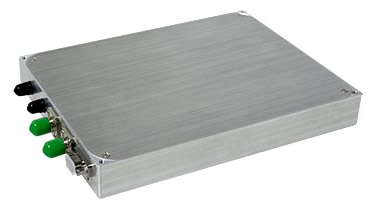
SCQ-RF broadband RF amplifier (or called as driver) is a desktop instrument specially designed for high-speed lithium niobate electro-optic modulator. This instrument can amplify the small high-speed signal level to the higher level that can drive the modulator, thus driving the lithium niobate (LiNbO3) electro-optic modulator to work, and has good gain flatness in the broadband range.
Features:
High bandwidth: 10, 20 or 40 GHz
Variable gain
The output range is up to 8V
Highly integrated
Easy to use
Applications:
10/20/40G optical modulating system
Fiber optic testing system
Optical fiber sensing system
Parameters of SCQ-RF-40 Driver
| Parameter | Unit | Min | Typ | Max |
| Transmission rate | Gb/s | 0.0001 | 44 | |
| Operating frequency range | Hz | 50K | 40G | |
| Output voltage magnitude | V | 7 | 8 | 9 |
| Gain margin | V | 0.3 | 0.4 | 0.6 |
| Regulation precision | dB | 24 | 27 | 35 |
| Output power P1dB | V | 0.1 | ||
| Gain variation(ripple) | dBm | 20 | ||
| Rise/fall time | dB | ±1.5 | ||
| Additional jitter | ps | 8 | 12 | |
| Input/output impedance | ps | 0.42 | ||
| Input voltage amplitude | | - | 50 | - |
Input voltage standing-wave ratio VSWR (75k to 10GHz) | 1.6:1 | 2.25:1 | ||
| Output voltage standing-wave ratio VSWR | 2:1 | 3:1 | ||
| Boundary dimension(L x W x H) | mm | 270 x 200 x 70 | ||
| Operating voltage | V | AC 220 | ||
| RF interface | V(f)-V(f) | |||
Limit Conditions
| Parameter | Unit | Min | Typ | Max |
| Input voltage amplitude | V | 1 | ||
| Working temperature | ºC | -10 | 60 | |
| Storage e temperature | ºC | -40 | 85 | |
| Humidity | % | 5 | 90 |
Eye Diagram
Ordering Information:
| SCQ | RF | XX | XX | X |
| SCQ series drivers | RF amplifier | Operating rate: 10---10Gbps 20---20Gbps 40---40Gbps | Output characteristic: Blank---Standard HO---High voltage output RZ---RZ signal amplification | Footprint: D---Table model |
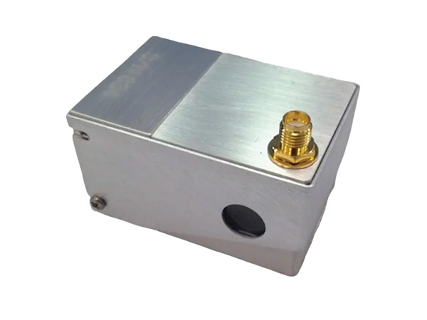
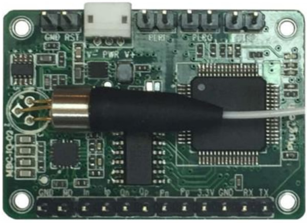
3.2 MZM Bias Controller
The bias controller is specially designed for Mach-Zehnder modulators to ensure a stable operation state in various operating environments. Based on its fully digitized signal processing method, the controller can provide highly stable performance. The controller injects a low frequency, low amplitude dither signal together with bias voltage into the modulator. It keeps reading the output from the modulator and determines the condition of the bias voltage and the related error. A new bias voltage will be applied afterwards according to the previous measurement. In this way, the modulator is ensured to work under proper bias voltage.
Features:
Bias voltage control on Peak/Null/Q+/Q−
Bias voltage control on arbitrary point
Ultra precise control: (1) 50dB maximum extinction ratio on Null mode; (2) ±0.5◦ accuracy on Q+ and Q− modes
Low dither amplitude: (1) 0.1% Vπ at NULL mode and PEAK mode; (2) 2% Vπ at Q+ mode and Q− mode
High stability: with fully digital implementation
Low profile: 40mm(W) × 30mm(D) × 10mm(H)
Easy to use: (1) Manual operation with mini jumper; (2) Flexible OEM operations through MCU UART2
Two different modes to provide bias voltage: (1) Automatic bias control; (2) User defined bias voltage
Application:
LiNbO3 and other MZ modulators
Digital NRZ, RZ
Pulse applications
Brillouin scattering system and other optical sensors
CATV Transmitter
Ordering Information
Part No.: SCQ-RF-BC
Remark: (1) The highest extinction ratio depends on and cannot exceed modulator maximum extinction ratio. (2) UART operation is only available on some version of the controller.
Performance:
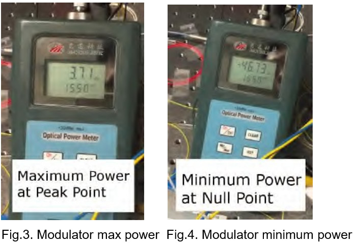
Maxim DC Extinction Ratio:
In this experiment, no RF signals were applied to the system. Pure DC extinction has been measured.
(1) Figure 3 demonstrates the optical power of modulator output, when modulator controlled at Peak point. It shows 3.71dBm in the diagram.
(2) Figure 4 shows the optical power of modulator output, when modulator controlled at Null point. It shows -46.73dBm in the diagram. In real experiment, the value varies around -47dBm; and -46.73 is a stable value.
(3) Therefore, the stable DC extinction ratio measured is 50.4dB.
Requirements for High Extinction Ratio:
(1) System modulator must have high extinction ratio. Characteristic of system modulator decides the maximum extinction ratio can be achieved.
(2) Polarization of modulator input light shall be taken care of. Modulators are sensitive to polarization. Proper polarization can improve extinction ratio over 10dB. In lab experiments, usually a polarization controller is needed.
(3) Proper bias controllers. In our DC extinction ratio experiment, 50.4dB extinction ratio has been achieved. While the datasheet of the modulator manufacture only lists 40dB. The reason of this improvement is that some modulators drift very fast. Our SCQ-RF-BC-ANY bias controllers update the bias voltage every 1 second to ensure fast track response.
Specifications:
| Parameter | Min | Typ | Max | Unit | Conditions |
| Control Performance | |||||
| Extinction ratio | MER 1 | 50 | dB | ||
| CSO2 | −55 | −65 | −70 | dBc | Dither amplitude: 2%Vπ |
| Stablization time | 4 | s | Tracking points: Null & Peak | ||
| Stablization time | 10 | s | Tracking points: Q+ & Q- | ||
| Electrical | |||||
| Positive power voltage | +14.5 | +15 | +15.5 | V | |
| Positive power current | 20 | 30 | mA | ||
| Negative power voltage | -15.5 | -15 | -14.5 | V | |
| Negative power current | 2 | 4 | mA | ||
| Output voltage range | -9.57 | +9.85 | V | ||
| Output voltage precision | 346 | µV | |||
| Dither frequency | 999.95 | 1000 | 1000.05 | Hz | Version: 1kHz dither signal |
| Dither amplitude | 0.1%Vπ | V | Tracking points: Null & Peak | ||
| Dither amplitude | 2%Vπ | V | Tracking points: Q+ & Q- | ||
| Input optical power3 | -30 | -5 | dBm | ||
| Input wavelength | 780 | 2000 | nm | ||
1 MER refers to Modulator Extinction Ratio. The extinction ratio achieved is typically the extinction ratio of modulator specified in modulator datasheet.
2 CSO refers to composite second order. To measure CSO correctly, the linear quality of RF signal, modulators and receivers shall be
ensured. In addition, the system CSO readings may vary when running at different RF frequencies.
3 Please be noted that input optical power does not correspond to the optical power at selected bias point. It refers to the maximum optical power that the modulator can export to controller when bias voltage ranges from −Vπ to +Vπ .
| Group | Operation | Explanation |
| Photodiode1 | PD: Connect MZM photodiode’s Cathode | Provide photocurrent feedback |
| GND: Connect MZM photodiode’s Anode | ||
| Power | Power source for bias controller | V-: connects the negative electrode |
| V+: connects the positive electrode | ||
| Middle probe: connects the ground electrode | ||
| Reset | Insert jumper and pull out after 1 second | Reset the controller |
| Mode Select | Insert or pull out the jumper | no jumper: Null mode; with jumper: Quad mode |
| Polar Select2 | Insert or pull out the jumper | no jumper: Positive Polar; with jumper: Negative Polar |
| Bias Voltage | Connect with the MZM bias voltage port | OUT and GND provide bias voltages for modulator |
| LED | Constantly on | Working under stable state |
| On-off or off-on every 0.2s | Processing data and searching for controlling point | |
| On-off or off-on every 1s | Input optical power is too weak | |
| On-off or off-on every 3s | Input optical power is too strong | |
| UART | Operate controller via UART | 3.3: 3.3V reference voltage |
| GND: Ground | ||
| RX: Receive of controller | ||
| TX: Transmit of controller | ||
| Control Select | Insert or pull out the jumper | no jumper: jumper control; with jumper: UART control |
1 Some MZ modulators have internal photodiodes. Controller setup should be chosen between using controller’s photodiode or using modulator’s internal photodiode. It is recommended to use controller’s photodiode for lab experiments for two reasons. Firstly, controller photodiode has ensured quality. Secondly, it is easier to adjust the input light intensity. Note: If using modulator’s internal photodiode, please make sure that the output current of photodiode is strictly proportional to input power.
2 Polar pin is used to switch the control point between Peak and Null in Null control mode(determined by Mode Select pin) or Quad+ and Quad- in Quad control mode. If jumper of polar pin is not inserted, the control point will be Null in Null mode or Quad+ in Quad mode. Amplitude of RF system will also affect the control point. When there is no RF signal or RF signal amplitude is small, controller is able to lock the work point to correct point as selected by MS and PLR jumper. When the RF signal amplitude exceeds certain threshold, polar of the system will be changed, in this case, the PLR header should be in the opposite state, i.e. the jumper should be inserted if it is not or pulled out if it is inserted.
Typical Application:
The controller is easy to use as follows:
Step1. Connect 1% port of the coupler to the photodiode of the controller.
Step2. Connect bias voltage output of the controller (through SMA or 2.54mm 2-pin header) to bias port of the modulator.
Step3. Provide controller with +15V and -15V DC voltages.
Step4. Reset the controller and it will start to work.
NOTE. Please be ensured that RF signal of the whole system is on before resetting the controller.
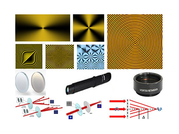
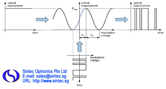
The basic construction of a modulator starts with a wafer made of lithium niobate. Embedded in the wafer is a waveguide used to direct the light through the modulator. At least two electrodes are placed on the top surface of the wafer near the waveguide. These electrodes are used to modulate the signal by utilizing the Pockels effect. Simply put, the Pockels effect is when an electric field applied to a crystal causes the refractive index to change. By changing the refractive index of the crystal, the light traveling through the waveguide changes phase which is used to modulate the signal.
We offer phase and intensity modulators. Our large variety of modulators makes it easy to find a suitable device for your project. The modulators we offer come with operational wavelengths from 850–1550nm and 3dB bandwidths ranging from 5– 50GHz. These high-performance modulators have a low insertion loss, high extinction ratio, can operate with high optical power, and offer excellent stability. Additionally, we offer modulators with PM outputs and low drive voltages to suit a wider variety of applications.
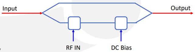
A phase modulator consists of a single waveguide seated in lithium niobate with two electrodes placed on either side of the waveguide (Figure below). This is the simplest type of modulator.
Out phase modulator is a high performance LiNbO3 modulator. This phase modulator can provide phase modulation with x-cut Annealed Proton Exchange (APE) process with a low driving voltage. It has low insertion loss and high transmission power. The modulator uses polarization maintaining input and output fibers, making it easy to integrate with other optical components. Contact us for more information
Features:
Polarization maintaining output
Low insertion loss (≤4.0dB)
High input power handling capability
Cabling 900µm tubing
Polarization extinction ratio ≥ 21dB
Applications:
Analog modulation
Pulse generation
Quantum photonic
Active mode locking laser
Specifications:
| Model | Wavelength (nm) | Bandwidth (GHz) | Maximum Input optical power (mW) | Vπ (V) | Optical return loss (≤ dB) | RF port connectors | Dimensions (mm) |
| STOL-PM-785-0.5 | 785 | 0.5 | 5 | 4V @ 1GHz | -30 | K connector | 96x25x16.3 |
| STOL-PM-785-5 | 785 | 5.0 | 5 | 5V@ 1GHz | -30 | K connector | 96x25x16.3 |
| STOL-PM-785-10 | 785 | 10 | 20 | 5.2V @ 1GHz | 30 | K connector | 96x25x16.3 |
| STOL-PM-785-20 | 785 | 20 | 5 | 6.8V @ 1GHz | 30 | K connector | 96x25x16.3 |
| STOL-PM-850-0.2 | 850 | 0.2 | 20 | 1.1V@0.1GHz | 40 | K connector | 65x11.5x5.8 |
| STOL-PM-1064-20 | 1064 | 20 | 300 | 5.5V @1GHz | 40 | V female | 87x14.5x10.1 |
| STOL-PM-1310-5 | 1310 | 5 | 50 | 6V @ 1GHz | 30 | K connector | 96x25x16.3 |
| STOL-PM-1310-10 | 1310 | 10 | 50 | 8.8V @ 1GHz | 30 | K connector | 96x25x16.3 |
| STOL-PM-1550-0.2-S | 1550 | 0.2 | 100 | 2.4V@10kHz | 45 | SMA female | 96x14x8.6 |
| STOL-PM-1550-5 | 1550 | 5 | 50 | 9V @ 1GHz | 30 | K connector | 96x25x16.3 |
| STOL-PM-1550-10 | 1550 | 10 | 40 | 10.5V @ 1GHz | 30 | K connector | 96x25x16.3 |
| STOL-PM-1550-0.5-PMLD | 1550 | 0.5 | 50 | 4V@0.001GHz | 30 | K connector | 96x25x16.3 |
Functional diagram:
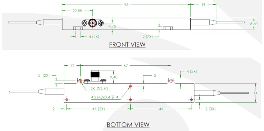
Mechanical drawing:
An intensity modulator uses the architecture of a Mach Zehnder interferometer (MZI) by splitting the waveguide into two paths and recombining them (Figure below). The electrodes are placed around the two waveguide paths to modulate the phase in the light while split. When the paths recombine, the light path undergoes either constructive or deconstructive interference depending on the phase, thereby modulating the light intensity.
Our Intensity modulator is designed for analog modulation of different frequency for satellite links, antenna remoting and RF over Fiber. By using Annealed Proton Exchange (APE) waveguide, the modulator provides low insertion loss and high-power handling capability. It features a highly linear transfer function and excellent extinction ratio. The modulator is compatible with a wide variety of modulator drivers and a separate bias port allows the modulator to operate at specific points of the transfer function.
Features:
Polarization Maintaining (PM) output or Single Mode (SM) output
Low insertion loss (≤ 4.5dB)
High input power handling capability
Low drive voltage
Applications:
Analog modulation
Pulse generation
Quantum photonics
Active mode locking laser
Specifications:
| Model | Wavelength (nm) | Bandwidth (GHz) | Max. Input optical power (mW) | Vπ (V) | Optical return loss (≤ dB) | RF port connectors | Dimensions (mm) |
| STOL-IM-785-0.5-PM | 785 | 0.5 | 10 | 2.5@1KHz | -45 | GPO male | 65 x 11.4 x 4.8 |
| STOL-IM-785-20-PM | 785 | 20 | 10 | 5.5@10GHz | -45 | V female | 87 x 14.5 x 10 |
| STOL-IM-785-40-PM | 785 | 40 | 10 | 6.5@20GHz | -45 | V female | 87 x 14.5 x 10 |
| STOL-IM-850-5-PM | 850 | 5 | 20 | 5.0@1GHz | -45 | V female | 87 x 14.5 x 10 |
| STOL-IM-850-10-PM | 850 | 10 | 20 | 5.0@1GHz | -45 | V female | 87 x 14.5 x 10 |
| STOL-IM-850-20-PM | 850 | 20 | 20 | 5.5@10GHz | -45 | V female | 87 x 14.5 x 10 |
| STOL-IM-1064-10-PM | 1064 | 10 | 100 | 4.3@10GHz | -45 | K female | 96.1 x 24.9 x 16.3 |
| STOL-IM-1064-20-PM | 1064 | 20 | 100 | 4.3@20GHz | -45 | K female | 96.1 x 24.9 x 16.3 |
| STOL-IM-1064-40-PM | 1064 | 40 | 300 | 3.9@1GHz | -50 | V female | 87 x 14.5 x 10 |
| STOL-IM-1310-10-PM | 1310 | 10 | 100 | 6.6@10GHz | -45 | K female | 66 x 22 x 9 |
| STOL-IM-1310-20-PM | 1310 | 20 | 100 | 5@1kHz | -45 | K female | 66 x 22 x 9 |
| STOL-IM-1310-40-PM | 1310 | 40 | 100 | 5.1@1GHz | -50 | V female | 87 x 14.5 x 10 |
| STOL-IM-1550-10-PM | 1550 | 10 | 100 | 6@1GHz | -45 | K female | 96 x 14 x 8.5 |
| STOL-IM-1550-10-PMV | 1550 | 10 | 100 | 6@1GHz | -45 | V female | 96 x 14 x 8.5 |
| STOL-IM-1550-10-SM | 1550 | 10 | 100 | 5@1GHz | -35 | SMA | 117.9 x 15.2 x 9.8 |
| STOL-IM-1550-20-SM | 1550 | 20 | 100 | 5.7@1GHz | -45 | K female/SMA | 96 x 24.9 x 16.3 |
| STOL-IM-1550-40-PM | 1550 | 40 | 100 | 4.5@30GHz | -45 | V female | 71 x 16 x 7 |
Options:
STOL-IM-785-40-PM-XX
XX HE: High Extinction Ratio
PD: internal PD
Please contact us for available options.
Functional diagram:
Mechanical drawing:
1. STOL-IM-XXX-XX-PM-PD housing, with internal PD

2. STOL-IM-XXX-XX-PM housing, no internal PD
Available accessories: ST-BCB-4
This is a compact bias control board designed to maintain the linear operating point of optical intensity modulators
The Multi-functional Integrated Optical Chip (MIOC) is the key component of Fiber Optic Gyroscope (FOG) for rotational rate sensing and inertial navigation systems. This Integrated Optic Chip device is composed of a polarizer, a Y-junction coupler and dual electro optic phase modulators. By using Lithium Niobate, the integrated optic chip is fabricated with Proton Exchange optical waveguides. It has features Polarization Extinction Ratio exceeding 60 dB that can minimize bias drift which results from polarization crosstalk induced non-reciprocity. The Fiber Optic Current Sensor (FOCS) chip is designed for fiber optic current sensing.
Features
1550±20nm operation
PM input and output port
Low insertion loss 3.5 dB
Polarization extinction ratio > 60dB
Low Vπ voltage 4V
Unpackaged chip available
Applications:
Fiber optic gyroscope (FOG)
Fiber optic current sensor (FOCS)
Hydrophone and other optic sensitive fields
Specifications:
| Model | Wavelength (nm) | Bandwidth (nm) | Split ratio (%) | Intensity modulation (%) | Insertion loss | Dimensions (mm) |
| STOL-MIOC-1550-BC | 1550 | 20 | 50 | 0.1 | 3.5 | 1x1.8x22.5 |
| STOL-MIOC-1550-BC-P | 1550 | 20 | 50 | 0.1 | 2.5 | 1x1.8x22.5 |
| STOL-MIOC-1550-PG | 1550 | 20 | 50 | 0.1 | 3.5 | 5.85x12.85x40.5 |
| STOL-MIOC-1550-PG-P | 1550 | 20 | 50 | 0.1 | 2.8 | 5.85x12.85x40.5 |
| STOL-MIOC-1550-SB | 1550 | 20 | 50 | 0.1 | 3.5 | 1.75x7x26 |
| STOL-MIOC-1550-SP | 1550 | 20 | 50 | 0.1 | 3.5 | 3x6.5x33 |
| STOL-FOCS-1550-PG | 1550 | 20 | 50 | 0.1 | 4.2 | 5.85x12.85x40.5 |
Functional diagram:
Mechanical drawing:
STOL-MIOC-1550-BC
Our high gain RF amplifier module offers cost-effective solutions for microwave and analog link. It is a compact and user-friendly module that provides a high quality, single ended voltage to drive optical modulator. Featuring a 12V or 5V DC power supply, this versatile module has an anodized. Precision-machined aluminium housing designed for efficient heat dissipation during prolonged use. Most of the modulator features a manually adjustable DC bias output voltage port, to further complement its effectiveness when used with a standard optical modulator.
Applications:
Analog RF amplification
5G wireless antenna
RF over fiber link
Digital modulation
General laboratory test and measurement
SONET/SDH
Specifications:
| Model | Bandwidth (GHz) | S11 Characteristics (dB) | Data rate (Gb/s) | RF Gain (dB) | Saturated output power (dBm) | Gain ripple (dB) | Input, output impedance (Ω) | Gain adjustment range (dB) | Power supply requirement |
| STOL-MD-9-M | 3 to 9 | -15 | - | 34 | 30 | 0.5 | 50 | - | 5V DC |
| STOL-MD-50E-M | 45 | -10 | 50 | 20 | 14.5 | 1.5 | 50 | 15 | 12V DC, 2A |
| STOL-MD-20-M | 18 | -10 | 23 | 19 to 24 | 26 | 0.5 | 50 | 5 | 12V DC, 1A |
| STOL-MD-12-DC | 12 | -10 | 12.5 | 14 to 26 | 26 | 1.5 | 50 | 6 | 12V DC, 1A |
Please contact us for more information.
Functional Diagram and Drawings:

A leading supplier and manufacturer of a wide range of photonics products such as lasers,laser parts & machines.
Office: 10 Bukit Batok Crescent #07-02 The Spire Singapore 658079
Tel: +65 63167112
Fax: +65 63167113
Whatsapp: +65 91904616