 English
 Français
 Deutsch
 euskara
 Русский язык
 Italiano
 Português
 Nederlands
 Polski
 Greek
Greek Lietuva
 Türkçe
 日本語
日本語 한어
한어 中文
中文 தாமில்
 فارسی
فارسی हिंदी
हिंदी Tiếng Việt
 ภาษาไทย
 Pilipino
 Indonesia
 தாமில்
Send us a message
CLOSE


")
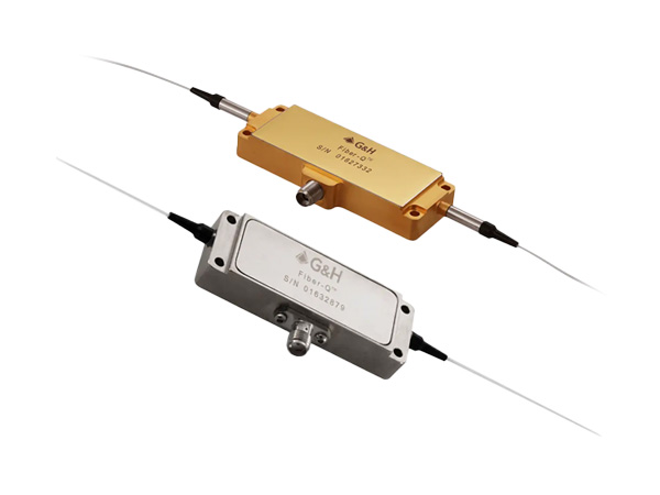
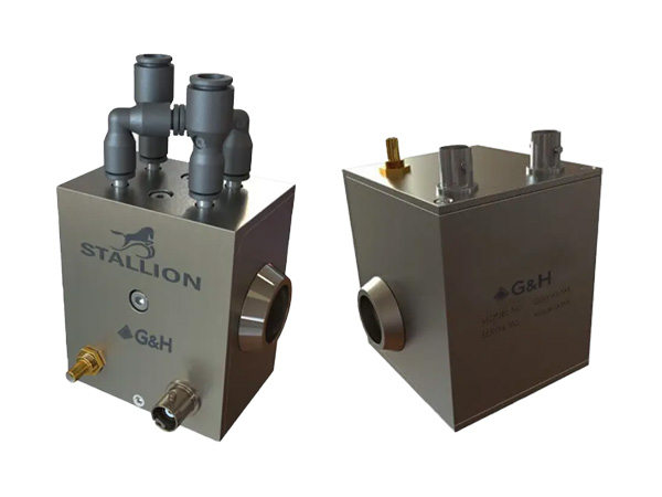
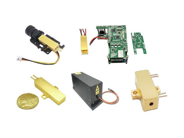
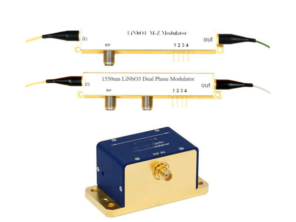
Q-switch drivers are used to drive Q-switches and their frequencies are mainly 24, 27, 41, 68, 80MHz etc.
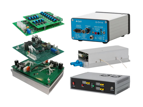
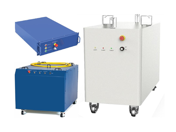
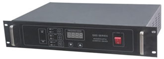
A high power RF driver module is available in output powers of 50W, 75W or 100W. Powered from 220VAC or 110VAC, the modulation inputs allow either full digital control or activation of an internal pulse generator. First pulse suppression is automatically implemented.
 Main Specifications:
RF power output : 50W, 75W or 100W
Frequency: 27.125MHz
VSWR: ≤1.2
Modulation repetition rate: 800Hz-50kHz
First pulse suppression
Modulation control inputs: digital TTL , till 100kHz
Driver over-heat, Q-Switch over-heat
Internal over-temperature protection and over-current protection
Digital display of frequency
Supply voltage input: 220VAC/110VAC, <150W
Dimension: 483x88x308mm
Weight: 8kg
Model Numbers: QSDxxyyZ
QSD - QSD series RF driver
XX - RF frequency, 27-27MHz, 24-24MHz
YY - RF output power (W), 50-50W, 75-75W
Z - others, Z or T
Example QSD-2720T (20W), QSD-2750T (50W), QSD-2775T (75W) or QSD-27100Z (100W)
Main Features of QSDxxyyT Series Digital Q-switch Drivers:
Newly designed digital RF driver has the following features comparing with analog version:
Touch panel,
Digital circuit to improve control accuracy with frequency resolution of 0.01Hz (0.001Hz or less upon request)
Internal trigger synchronizing with laser, to achieve perfect marking
Integrated open load protection
Easier and more accurate panel controlled laser delay.
Other power levels are available upon request.
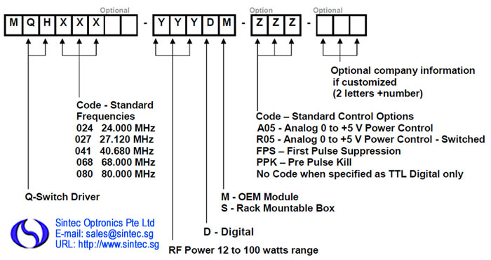
Former Model Number: R390XX-YYDMZZZ-A
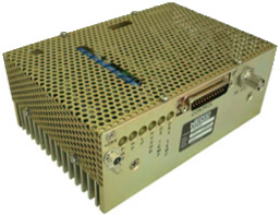
The MQH0XX-YYDM-ZZZ module is a high power RF driver, designed to drive a Q-switch. The driver has two digital modulation inputs: Fixed and Variable. These controls allow the customer to issue a pulse command of a "Fixed" pulse width, the duration determined by the Driver's pulse width control, settable by the customer, or issue a "Variable" pulse command, the duration determined by the input signal’s pulse width. The output power is controlled by the analog input, where the mode of operation is defined by ZZZ = A05 normal analog mode, or R05 analog switched to full RF mode or a triggered RF Ramp Down mode where ZZZ = FPS first pulse suppression mode or PPK pre-pulse kill mode. The choices of Frequency (XX), Output Power (YY), and Power Control (ZZZ) option are "Factory Set" when ordered. The RF Driver requires forced air cooling.
The product delivered will be manufactured to be compliant with EU Directive 2002/95/EC for Reduction of Hazardous Substance. The product will be manufactured to other standards upon customer request.
24, 27.12, 40.68, 68, or 80 MHz RF frequency (XX)
0.01% Quartz Stabilized
Up to 100* watts RF power output (YY)
Two TTL Digital Modulation Inputs: fixed and variable pulse width.
Analogue Modulation or Triggered RF Ramp Down Mode (ZZZ)
Up to 100 kHz Pulse Rate.
Fault Protection on Low Power, High Power, and High VSWR
Operates on 28 VDC
RF Driver for an Acousto-Optic Q-Switch Device used to spoil the “Q” of a CW laser so as to output an intense pulse of light.
Used in industrial, medical, or military applications.
| RF Frequency: | 24.00, 27.12, 40.68, 68.00, 80.00 MHz ± 0.01% |
| Spurious Levels: | -50 dBc maximum |
| Harmonic Distortion | -30 dBc maximum |
| Digital Inputs: | |
| Fixed Mod In | TTL Levels, Triggered on Rising Edge. Pulse Width Applied >50 ns. |
| Variable Mod In | TTL Levels, TTL High = RF off |
| Extinction Ratio: | 35 dB minimum |
| RF Rise Time 10% to 90% | 500 ns maximum |
| RF Fall Time: 90% to 10% | 100 ns maximum |
| Modulation Repetition Rates: | 1 Hz to 100 kHz for Fixed Modulation; DC to 100 kHz for Variable Modulation |
| Fixed Modulation Output Pulse Width Adjustment Range: | 1 to 14 ms, Customer Adjustable |
| Available Pulse Control Options: | ZZZ = Mode |
| Pulse Control Mode is "Factory Set When Ordered": | FPS = First Pulse Suppression PPK = Pre Pulse Kill A05 = Analog Control R05 = RF Switched to Analog Control ___ = Digital Modulation Only |
| FPS Trigger / Analog input | Units configured with FPS, PPK: TTL Levels, Triggered on TTL Rising Edge. Units configured with A05, R05: 0 to 5 volts analog. |
| *RF Output Power "Factory Set When Ordered": | YY = 50 or 100 watts nominal for 24, 27, 41, and 68 MHz units Adjustable from 25 to 100 watts. 50 watts nominal for 80 MHz units, Adjustable from 20 to 50W |
| Output Impedance: | 50 ohms nominal |
| Shutter Output: | 0.3 sec delay. Opens on fault. Capable of sinking 1 amp at 28 volts Maximum. |
| Supply Voltage Input | +28 VDC ± 1% |
| Supply Current Input | 6.5 A for 50 W units 9.0 A for 100 W units |
| Operating Temperature | +10°C to +55°C |
| Air Flow through Heat Sink | > 36 CFM (> 17 litres / second) @ 25°C |
Maximum Ratings:
| Supply Voltage: | 30 volts DC maximum | ||
| Power Output: | No DC Feedback Allowed | ||
| Storage Temperature: | -20°C to +85°C |
| CONNECTORS & MECHANICAL: | Located on front panel | |
| RF Output Connector: | BNC Female | |
| Power Supply Connections: | Vcc, | Solder Post |
| Return | Ground Lug | |
Ordering Codes: Example: MQH027-100DM-A05, A 27 MHz RF Driver with two TTL digital Modulation inputs (fixed and variable pulse width) and an analog input (A05) which enables control of the RF output power. Designed to Drive an AO Q-switch requiring 100 watts RF Power or less. Delivered as a RoHS compliant, forced air cooled OEM Module.
Output RF frequency options: xxx = 24, 27, 41, 68, 80, 110MHz
RF power: yy = 2 - - - 24W
Control Option: ZZZ (For more infomation on ow to select a pulse control. )
Output RF frequency options: XX = 24, 27, 41, 68, 80, 110, RF frequency = 24.00 MHz, 27.12 MHz, 40.68 MHz, 68MHz, 80MHz or 110MHz
RF power: yy = 2 - - - 24, 2 to 24 watts, Factory set to match the matching Q-Switch
The driver is factory set when ordered with a control option, which determine the type of control of the output power. The options available that control the RF output level for the drivers include:
Control Option: zzz
FPS = First Pulse Suppression
PPK = Pre Pulse Kill
R05 = RF off Analog Control
A05 = Analog Control
aaV: supplu voltage, 12V, 15V or 24V
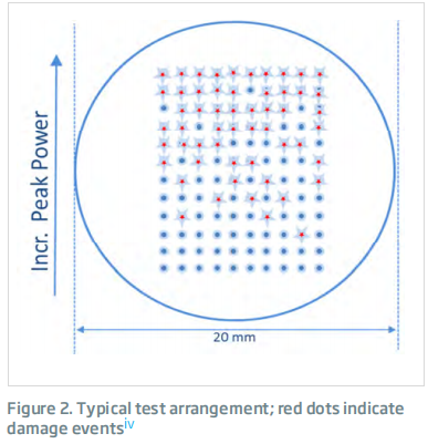
The option available for the driver is factory set, and is specified by the last three letters of the model number. When the FPS or PPK control option is selected, the circuit is designed to eliminate the large light pulse that is output from the laser after a long period of inactivity. Normally, the first pulse from a Q-Switched laser that has been held off for over 100 ms will be much larger than the subsequent pulse. This excess energy can cause unwanted damage to the target of the laser. The circuit does this by scaling the energy sent to the Q-Switch. The result is that this first pulse has the lower energy compared to the subsequent pulses. When the A05 or R05 control option is selected, the circuit is designed to control the output with an analog input signal allowing intensity control of any pulse. This control is used to vary the output energy of the laser pulse.
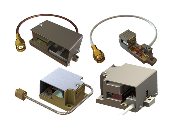
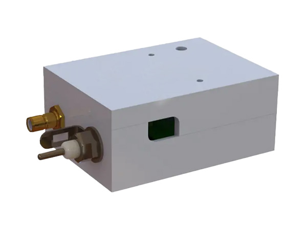
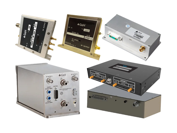
A compact high power RF driver module is available in output powers of 50 or 100W. Powered from 28VDC, the modulation inputs allow either full digital control or activation of an internal pulse generator. First pulse suppression is implemented through either analogue modulation, RF off analogue control, triggered first pulse suppression, or triggered pre-pulse kill, as described in our FPS guidance notes. On board LED’s and TTL logic outputs monitor driver status and cooling is through forced air over the heat sink.
| Parameter | Specification |
| Output Frequency: | xx = 24, 27, 41, 68, 80, 110. Where RF Frequency = 24.00, 27.12, 40.68, 68, 80, 110 MHz ± 0.01% |
| Spurious Levels: | -50 dBc Maximum |
| Harmonic Distortion | -20 dB Maximum |
| Modulation Input | |
| Mod In Fixed (pin 3 ) | TTL Levels Triggered on TTL Rising Edge. Pulse Width Applied >50 ns. |
| Mod In Variable (pin 5) | TTL Levels TTL HIGH = RF Off |
| Extinction Ratio: | 40 dB Minimum |
| RF Rise Time 10% to 90% | 100 ns Maximum |
| RF Fall Time: 90% to 10% | 50 ns Maximum |
| Modulation Repetition Rates: | 1 Hz to 500 kHz for Fixed Modulation DC to 500 kHz for Variable Modulation |
| Fixed Modulation Output Pulse Width Adjustment Range: | 1 to 20 μs, Customer Adjustable |
| Available Pulse Suppression Modes: | zzz = Mode |
| Modulation Operating Mode is "Factory Set" Internally. | FPS = First Pulse Suppression PPK = Pre Pulse Kill R05 = RF Switched to Analog Control A05 = Analog Control |
| FPS Trigger (pin 2) for Pulse Suppression for Units Configured with FPS, PPK: | TTL Levels, Triggered on TTL Rising Edge |
| Analog in (pin 6) for Power Control for Units Configured with A05, R05 | 0 to 5 volts Analog |
| Enable - Stand by Mode (pin 11) | < 3 watt dissipation in stand by mode. TTL High or no connection = Normal operation TTL Low = Stand by Mode Momentary TTL Low = Driver Reset - after fault is removed. |
| Zero Crossing Enable (pin 7) normally: | TTL high or no connection- disabled, TTL low- enabled |
| If model # is (-ZC): | TTL high or no connection- enabled, TTL low- disabled |
| Sync out (pin 1 ) | Outputs 3.3 volt signal |
| RF Power Output: | YY watts where YY = 2 to 24 watts |
| Output Impedance: | 50 Ω |
| Supply Voltage: | +15 VDC (or 24V) |
| Supply Current: | < 3 amps. |
| OPERATING TEMPERATURE: | +10 to +55 0C Case Temperature |
| Contact Cooled | The Driver must be attached to a heatsink capable of dissipating 25 watts |
| MAXIMUM RATINGS: | |
| Supply Voltage: | +18 volts |
| Power Output: | No DC Feedback Allowed |
| Storage Temperature: | -20 to + 850C |
| Dimension | 95x80x25mm |
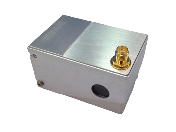
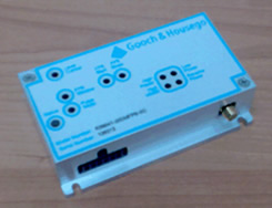
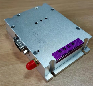
SQDRxxx-yyDC-zzz-aaa series RF drivers are similar to QC0xx-yyDC-zzz drivers but cheaper.
xxx is operation frequency (xxx=041 means 40.68MHz and xxx=080 means 80MHz), yy is maximum output RF power (yy=20 means 20W), D means digital modulation, C means compact size, zzz means operation mode (FPS, PPK, A05 or A05, FPS is default. For more information), aaa is input voltage (aaa=15V means input voltage is 15VDC).
The outline dimension is 95x70x25mm.
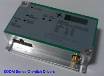
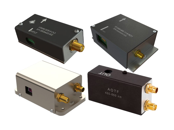
SQDMxxx-yyW-aaV-zzz series RF drivers are similar to QCxxx-yyDC-zzz drivers but cheaper. Their outlines are similar too.
xxx is operation frequency in MHz (xxx=041 means 40.68MHz and xxx=080 means 80MHz), yy is maximum output RF power (yy=20 means 20W), aa means input voltage (aa=15 means 15VDC input, zzz means operation mode (FPS, PPK, RPS or APS, PPK is default. For more information). For example, SQDM041-20W-15V-PPK means operation frequency 40.68MHz, output RF power 20W, input voltage 15V and operation mode PPK.. The outline dimensions are 95x70x25mm.
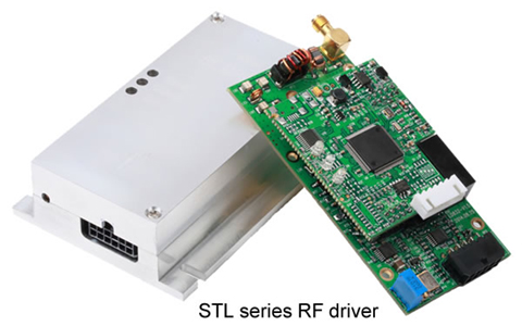
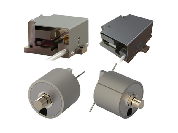
| Part number | STL-LD832 | STL-LD882 |
| Output Frequency | 80MHz,±0.01% (100ppm) | 80MHz,±0.01% (100ppm) |
| Output Power | >15.0W @50Ω | >15.0W @50Ω |
| Modulation Input | TTL, 1Hz to 1.2MHz | TTL, 1Hz to 1.2MHz |
| Sync Out Level | 3.3V ±5% | 3.3V ±5% |
| Supply Voltage | +12V ±5% | +24V ±5% |
| Supply Current | <2.20A | <2.20A |
| Spurious Levels | -50dBc Maximum | -50dBc Maximum |
| Harmonic Distortion | -20dB Maximum | -20dB Maximum |
| Extinction Ratio | 40dB Maximum | 40dB Maximum |
| RF Rise Time 10% to 90% | <25ns | <25ns |
| RF Fall Time 90% to 10% | <25ns | <25ns |
| Operation Temperature | +10oC to +50 oC | +10oC to +50 oC |
| Storage Temperature | -20 oC to +85 oC | -20 oC to +85 oC |
| Dimension | 103.8x84.1x25mm | 103.8x84.1x25mm |
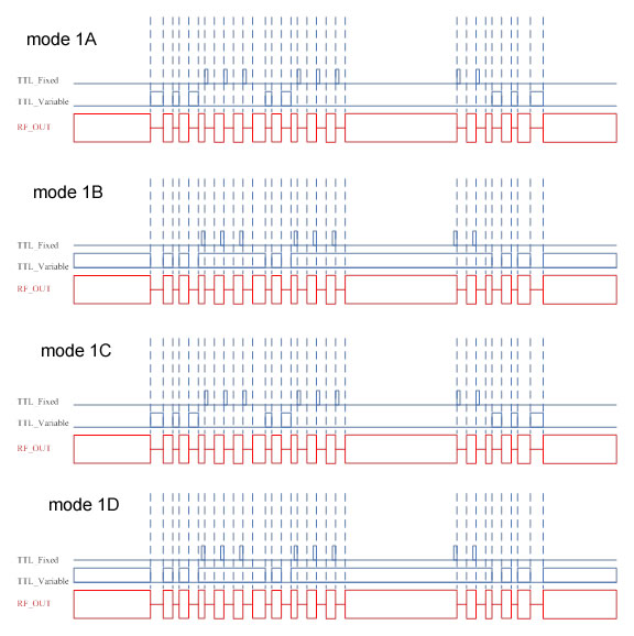
There are 5 potential meters to change the settings as follows:
Prf: setting the RF output power
Pulse Width: setting the pulse width of TTL_Fixed selection with the range 0.8us~25us±10%
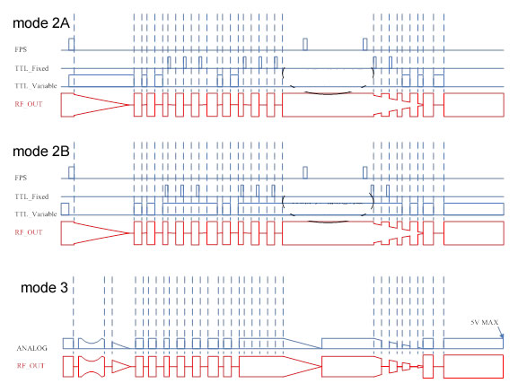
FPS Window: FPS window time and its range is 20us~350us±10%
FPS Slope: setting the FPS slope
FPS Start:setting FPS starting point
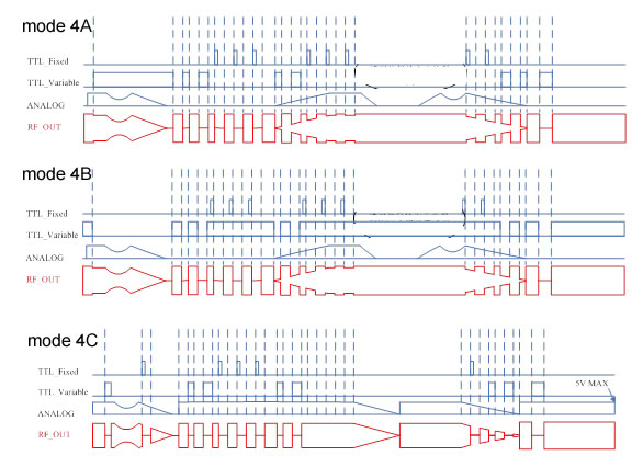
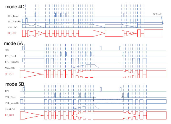
There are 13 RF output modes as follows:
Technical Specifications:
Input electricity: 15~24VDC, ripple £100mV
FPS, TTL_Fixed, TTL_Varibale input resistance 10kΩ±10%
ANALOGinput resistance 10kΩ±10%
FPS, TTL_Fixed, TTL_Varibale low level -0.5~0.8V, high level 2.5~5V
ANALOG input voltage 0~5V
FPS’s input width 1~350uS
TTL_Fixed input range 50ns, period -500ns
TTL_Variable effective input range 500ns, period -500ns
TTL_Fixed output range 0.8us~25us±10%, determined by Pulse Width potential meter
Shortest RF operation time 500ns
Shortest lasing time 500ns
RF fall time <20ns
FPS window range 20~350us±10%
Max. RF output Pmax=20W±10%, max. input electrical power 45W±10%
Adjustable output RF power range 0~Pmax, determined by Prf potential meter
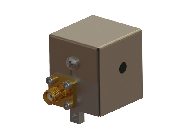
Outline dimension: 100x70x25mm
Part numbers: STZxxx-yyD-zzz
XXX: RF operation frequency, xx=041(40.68MHz) or =80(80MHz)
YY: output RF power (yy=2-20, W)。
ZZZ: first pulse suppression mode (zzz=FPS, TTLF or TTLV)
D: D means digital input modulation, A means analog input modulation
A leading supplier and manufacturer of a wide range of photonics products such as lasers,laser parts & machines.
Office: 10 Bukit Batok Crescent #07-02 The Spire Singapore 658079
Tel: +65 63167112
Fax: +65 63167113
Whatsapp: +65 91904616