 English
 Français
 Deutsch
 euskara
 Русский язык
 Italiano
 Português
 Nederlands
 Polski
 Greek
Greek Lietuva
 Türkçe
 日本語
日本語 한어
한어 中文
中文 தாமில்
 فارسی
فارسی हिंदी
हिंदी Tiếng Việt
 ภาษาไทย
 Pilipino
 Indonesia
 தாமில்
Send us a message
CLOSE
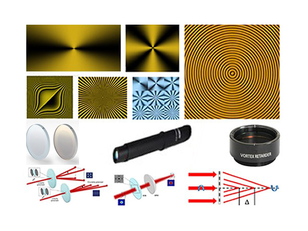


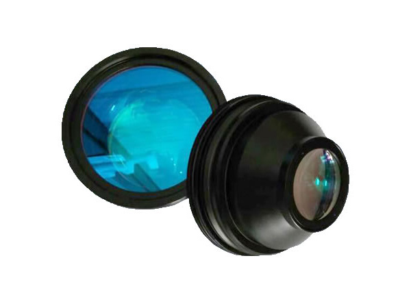

A Spatial Light Modulator (SLM) is an electrically programmable device that modulates light according to a fixed spatial (pixel) pattern. SLMs have an expanding role in several optical areas where light control on a pixel-by-pixel basis is critical for optimum system performance. They are used in various applications like optical processing, data routing, and information display.
SLMs can work through different methods in materials such as liquid crystals (LC). LC-based SLMs have advantages like high birefringence and low-voltage operation, allowing for large optical effects in thin layers. They can create large arrays operating at high data rates, even though individual pixels switch quickly. Integrating LCs with silicon backplanes is a key technology for smart pixel devices, combining detectors, electronic logic, and modulators into a single device.
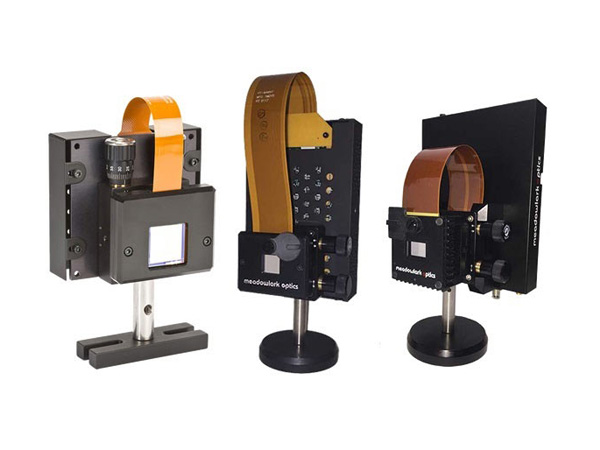
Sintec Optronics is the authorized distributor of Meadowlark Optics’ liquid crystal on silicon (LCoS) spatial light modulators in Southeast Asia and India. Meadowlark Optics’ LCoS SLMs boast exceptional speed, efficiency, and high resolution, ensuring accurate and reliable results. They are uniquely designed for pure phase applications and incorporate analogue data addressing with high refresh rates. This combination provides users with the fastest response times and highest phase stabilities commercially available. Phase-only SLMs can also be used for amplitude-only modulation or take advantage of the rectangular aperture for simultaneous phase and amplitude modulation.
Selection Guide
| Models | Series / Versions | Optional Add-Ons |
| 1920 x 1200 Analog SLM |
|
|
| 1024 x 1024 Analog SLM |
| |
| 1536 x 1536 Mid-wave Nematic SLM |
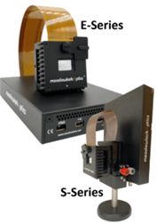
E-Series: Education, Economical and Entry-level
S-Series: 10-bit, High Efficiency, High Power
The E-Series SLM a good entry point into our SLM offerings. The standard S-Series offers additional features, including 10-bit operation, dielectric mirror coatings for improved efficiency, and liquid cooling.
SLM Features
High resolution
High phase stability, pure analogue phase control
High first-order efficiency, high reflectivity
High power handling
Wavelengths from 400 – 1650nm
Software Features
Output triggers
Image generation
Automated sequencing
Wavefront calibration
Global and regional look up tables
Dynamic Recalibration Kit for quick optimization
SLM Specifications
Resolution: 1920 x 1200
Array Size: 15.36 x 9.60mm
Pixel Pitch: 8.0 x 8.0µm
Backplane Refresh: 1.35kHz
Fill Factor: 95.6%
0th Order Diffraction Efficiency: 76 – 91%
0th Order Diffraction Efficiency: 92 – 98% (dielectric mirror)
Controller: HDMI E-Series: 8-bit, S-Series: 10-bit
| Standard Calibration Wavelengths | STANDARD SPEED Liquid Crystal Response Time | Calibrated Wavefront Distortion | ||
| AR Coating 400 – 800nm | AR Coating 500 – 1200nm | AR Coating 850 – 1650nm | ||
| 405nm | ≤ 14.0ms | – | – | λ/5 |
| 532nm | ≤ 15.0ms | ≤ 19.0ms | – | λ/7 |
| 635nm | ≤ 15.0ms | ≤ 20.0ms | – | λ/8 |
| 785nm | ≤ 16.0ms | ≤ 23.0ms | – | λ/10 |
| 1064nm | – | ≤ 33.0ms | ≤ 40.0ms | λ/10 |
| 1550nm | – | – | ≤ 55.0ms | λ/12 |
Ordering Code
| Series | P/N | AR Coating | Controller |
| E-Series | E19x12 | 400-800 500-1200 850-1650 | HDM8 |
| S-Series | S19x12 | HDM10 | |
| S-Series with Dielectric Mirrors | SDM19x12 | HDM10 | |
| Optional Add-ons |
| ||
E.g.: E19x12-400-800-HDM8-WCS1: E-Series SLM with 400-800nm coating, HDMI 8-bit controller, with liquid cooling system
High Speed Analog, Phase Only – up to 1.7kHz
The 1024 x 1024 SLM is good for applications requiring high speed, high diffraction efficiency, low phase ripple and high-power lasers.
SLM Features
High resolution
High speed
High phase stability
Pure analogue phase control
High first order efficiency
High reflectivity
High power handling
On-board Memory
Wavelengths from 488–1650nm
Software Features
Input and output triggers
Image generation
Automated sequencing
Wavefront calibration
Global and regional look up tables
Temperature monitoring
Dynamic Recalibration Kit
SLM Specifications
Resolution: 1024 x 1024
Array Size: 17.40 x 17.40mm
Fill Factor: 97.2%
Pixel Pitch: 17 x 17μm
Zero-Order Diffraction Efficiency: 75 – 87%
With Dielectric Mirror Coating:92 – 98%
| Standard calibration wavelength | HIGH SPEED Liquid Crystal Response Time | Calibrated wavefront distortion | ||
| AR coating range 488-850nm | AR coating range 500-1200nm | AR coating range 850-1650nm | ||
| 532nm | ≤ 1.0ms | ≤ 1.4ms | – | λ/5 |
| 635nm | ≤ 1.3ms | ≤ 1.8ms | – | λ/6 |
| 785nm | ≤ 1.8ms | ≤ 2.4ms | – | λ/7 |
| 1064nm | – | ≤ 3.4ms | ≤ 6.0ms | λ/10 |
| 1550nm | – | – | ≤ 9.0ms | λ/12 |
| Standard calibration wavelength | ULTRA HIGH SPEED Liquid Crystal Response Time | Calibrated wavefront distortion | ||
| AR coating range 488-850nm | AR coating range 500-1200nm | AR coating range 850-1650nm | ||
| 532nm | ≤ 0.6ms | ≤ 0.7ms | – | λ/5 |
| 635nm | ≤ 0.7ms | ≤ 0.9ms | – | λ/6 |
| 785nm | ≤ 0.9ms | ≤ 1.2ms | – | λ/7 |
| 1064nm | – | ≤ 1.7ms | ≤ 2.0ms | λ/10 |
| 1550nm | – | – | ≤ 3.9ms | λ/12 |
Ordering Code
| Series | P/N | AR Coating | Controller |
| High Speed | HSP1K | 488-850 500-1200 850-1650 | PC8 |
| High Speed, High Efficiency with Dielectric Mirrors | HSPDM1K | ||
| Ultra High Speed | UHSP1K | ||
| Ultra High Speed, High Efficiency with Dielectric Mirrors | UHSPDM1K | ||
| Optional Add-ons |
| ||
E.g.: HSP1K-488-850-PC8-WCS1: High Speed 1024x1024 SLM with 488-850nm coating, PCIe 8-bit controller, with liquid cooling system
Ultra-High Power – ≥ 1kW at 1070nm
High average power handling - The newest SLM boasts CW power handling of ≥ 1kW at 1070nm. In tests at SPICA, the SLM retained its full >1 wave range of phase modulation at powers up to 1.4 kW. With sapphire cover glass, built-in water cooling and a suite of calibration tools, the high power SLM can maintain calibrated performance under extreme laser power loads.
SLM Features
17.4 x 17.4mm active array
1024 x 1024 pixel count
97.20% fill factor
Water -cooled
TEC active heat dissipation
AR-coated sapphire cover glass
Dielectric mirrored backplane
750 – 850 nm or 980 – 1150 nm
Pure analogue phase control
On-board Memory
Software Features
Input and output triggers
Image generation
Automated sequencing
Wavefront calibration
Global and regional look up tables
Temperature monitoring
Look-up-table Calibration Kit
Specifications
Resolution: 1024 x 1024
Array Size: 17.40 x 17.40mm
Zero-Order Diffraction Efficiency: 95% (at 1064nm)
Fill Factor: 97.2%
Pixel Pitch: 17 x 17μm
Standard calibration wavelengths | Coating range | Average power rating | HIGH AVERAGE POWER Liquid crystal response time vs operating temperature | ||
| 19 C | 44 C | 70 C | |||
| 785nm | 750 - 850nm | (tests pending) | (tests pending) | (tests pending) | (tests pending) |
| 1064nm | 980 - 1150nm | ≥ 1000W (at 1070nm) | ≤ 100ms | ≤ 22ms | ≤ 8. ms |
Ordering Code:
| Series | P/N | AR Coating | Controller |
| Ultra-high-power, with dielectric mirrors | UHPDM1K | 750-850 980-1150 | PC8 |
| Optional Add-ons | -WCS1: Liquid Cooling System (Ambient) -TCS2: TEC Heater for Variable Temperature Heating -TCS3: WCS and TCS2 for Variable Temperature Cooling -CAL: Additional Calibration Wavelength -NI: Dynamic Recalibration Tool | ||
E.g.: UHPDM1K-750-850-PC8: Ultra-high-power 1024x1024 SLM with 750-850nm coating, high-efficiency dielectric mirrors, PCIe 8-bit controller, with liquid cooling system
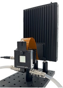
Custom designed for high-speed neuroscience applications
Pixel Count: 1536 x 1536
Array Size: 30.7 x 30.7mm
Pixel Pitch: 20µm x 20µm
Pixel Voltage: 12V
Fill Factor: 96%
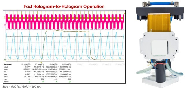
Maximum GS Hologram Frame Rate at 1064nm: 600fps
(1000 fps available at reduced efficiency)
Trigger Response for On-board Holograms: 6µs latency / 3 – 9µs jitter
The High-Speed 1536 x 1536 SLM, combining high pixel count and high frame rate with efficient diffraction. By building on success with other models, the 1536 x 1536 SLM leverages the same pixel design in a reduced array size format for even faster addressing.
The 1536 x 1536 SLM is built for speed. It uses large high-voltage, high-capacitance pixels which are essential for increasing switching speed. These factors also serves to reduce fringing field effects and phase ripple to improve photostimulation efficiency, especially at large diffraction angles. To optimize performance, the entire SLM head is thermally controlled for operation at elevated temperatures.
The SLM drive electronics receive 8-bit 1536 x 1536 phase masks from the host computer over a 16-bit PCIe pipeline for fast transfer rates. For further speed enhancement, a library of up to 2,045 user-specified phase masks can be stored on the driver board and then selected in any sequence using on-board OverdrivePlus transition calculation.
These capabilities work together to provide hologram-to-hologram frames rates of up to 600fps at 89% of steady-state diffraction efficiency. Frame rates of up to 1,000fps have been demonstrated with commensurate decreases in diffraction efficiency.
A leading supplier and manufacturer of a wide range of photonics products such as lasers,laser parts & machines.
Office: 10 Bukit Batok Crescent #07-02 The Spire Singapore 658079
Tel: +65 63167112
Fax: +65 63167113
Whatsapp: +65 91904616