 English
 Français
 Deutsch
 euskara
 Русский язык
 Italiano
 Português
 Nederlands
 Polski
 Greek
Greek Lietuva
 Türkçe
 日本語
日本語 한어
한어 中文
中文 தாமில்
 فارسی
فارسی हिंदी
हिंदी Tiếng Việt
 ภาษาไทย
 Pilipino
 Indonesia
 தாமில்
Send us a message
CLOSE
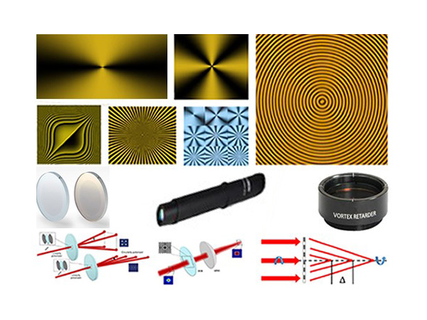


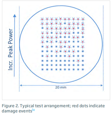

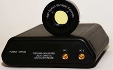
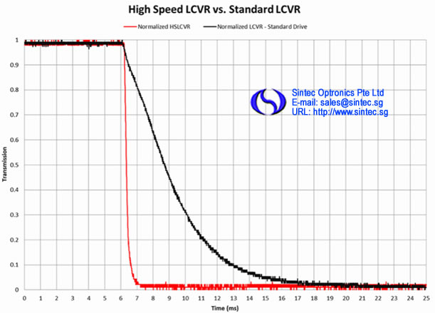
Sintec Optronics newest liquid crystal (LC) product, the high speed LC variable retarder (HS LCVR) has a 10X speed improvement over our award winning standard LCVR. The sub-millisecond speeds are achieved without the 50/50 duty cycle drive scheme required by our ferroelectric liquid crystal components, but are nearly as fast. The new LCVR uses nematic liquid crystal materials to electrically control polarization and provide tunable retardation by changing the effective birefringence of the material with applied voltage, thus altering the input polarized light to any chosen elliptical, linear or circular polarization. Our precision HS LCVR requires unique fabrication and assembly steps. We construct these retarders using optically flat fused silica windows coated with our transparent conductive Indium Tin Oxide (ITO). Our ITO coating is specially designed for maximum transmission from 400 – 700 nm. Liquid Crystal Variable Retarder response time depends on several parameters, including layer thickness, viscosity, temperature, variations in drive voltage and surface treatment. Liquid crystal response time is proportional to the square of the layer thickness and therefore, the square of the total retardance.
Sub-millisecond speeds
Standard LC Drive Schemes
Includes heated housing
Precision non-mechanical retardation control
| Retarder Material | Nematic liquid crystal |
| Substrate Material | Optical quality synthetic fused silica |
| Wavelength Range | 450 - 700 nm |
| Typical LC Rise Time (10 – 90%) | 50 µs @ 532 nm |
| Typical LC Fall Time (90 – 10%) | 500 µs @ 532 nm |
| Retardance | 0 to λ/2 |
| Transmitted Wavefront Distortion (at 632.8 nm) | ≤ λ/4 |
| Surface Quality | 40-20 scratch-dig |
| Beam Deviation | ≤ 2 arc min |
| Reflectance (per surface) | ≤ 0.5% at normal incidence |
| Temperature Range | 50°C |
| Recommended Safe Operating Limit | 500 W/cm 2, CW; 300 mJ/cm2, 10 ns, visible |
| Diameter, D (in.) | Clear Aperture, CA (in.) | Thickness, t (in.) | Part Number |
| 2 | 0.8 | 0.75 | STM-HSLRC-200 |
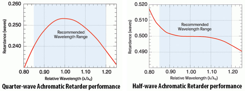
Sintec Optronics Precision Achromatic Retarders are designed to provide a nearly constant retardance over a broad wavelength region. Standard quarter- and half-wave devices are available for common wavelength regions in the visible and near infrared.
Features:
Broad spectral range
Superior field of view
Technical specifications:
| Retarder Material | Birefringent Polymer |
| Substrate Material | N-BK7 |
| Standard Wavelengths | |
| 545 | (485-630 operating range) |
| 630 | (555-730 operating range) |
| 720 | (630-835 operating range) |
| 840 | (735-985 operating range) |
| 1060 | (920-1240 operating range) |
| 1400 | (1200-1650 operating range) |
| Custom Wavelengths | 400-1800 nm (specify) |
| Retardance | λ/4 and λ/2 |
| Retardance Accuracy | ≤ λ/100 |
| Transmitted Wavefront Distortion | ≤ λ/4 |
| Surface Quality (scratch-dig) | 40-20 |
| Beam Deviation | ≤ 1 arc-min |
| Reflectance (per surface) | ≤ 0.5% at normal incidence |
| Threshold | 500 W/cm2, CW; 600 mJ/cm2, 20 ns, visible; 4 J/cm2, 20 ns, 1064 nm |
| Operating Temperature | -20˚C to +50˚C |
| Mounted | |||
| Clear Aperture in. [mm] | Dimensions ± 0.005 in. [± 0.13 mm] | Thickness ± 0.020 in.[±0.51 mm] | Part Number |
| Quarter Wave | |||
| 0.4 [10.2] | Ø1.00 [Ø25.4] | 0.25 [6.35] | STM-AQM-050-λ |
| 0.7 [17.8] | Ø1.00 [Ø25.4] | 0.35 [8.9] | STM-AQM-100-λ |
| 1.2 [30.5] | Ø2.00 [Ø50.8] | 0.5 [12.7] | STM-AQM-200-λ |
| Half Wave | |||
| 0.4 [10.2] | Ø0.50 [Ø12.7] | 0.25 [6.4] | STM-AHM-050-λ |
| 0.7 [17.8] | Ø1.00 [Ø25.4] | 0.35 [8.9] | STM-AHM-100-λ |
| 1.2 [30.5] | Ø2.00 [Ø50.8] | 0.5 [12.7] | STM-AHM-200-λ |
| Unmounted | |||
| Clear Aperture in. [mm] | Dimensions =+ 0/-0.01 [+0/-0.25mm] | Thickness ± 0.020 in. [±0.51 mm] | Part Number |
| Quarter Wave | |||
| 0.4 [10.2] | Ø0.50 [Ø12.7] | 0.14 [3.6] | STM-AQ-050-λ |
| 0.8 [20.3] | Ø1.00 [Ø25.4] | 0.28 [7.1] | STM-AQ-100-λ |
| 1.6 [40.6] | Ø2.00 [Ø50.5] | 0.5 [12.7] | STM-AQ-200-λ |
| Half Wave | |||
| 0.4 [10.2] | Ø0.50 [Ø12.7] | 0.14 [3.6] | STM-AH-050-λ |
| 0.8 [20.3] | Ø1.00 [Ø25.4] | 0.28 [7.1] | STM-AH-100-λ |
| 1.6 [40.6] | Ø2.00 [Ø50.5] | 0.5 [12.7] | STM-AH-200-λ |
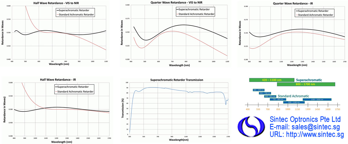
Sintec Optronics is proud to introduce our new Precision Superachromatic Retarder - now with the broadest wavelength coverage of our entire retarder product line. These are available standard for two wavelength ranges - 420 to 1100 nm and 800 to 1700 nm - and in both quarter and half wave retardances. Custom devices are available for other wavelength ranges and retardances. Stock items are not anti-reflection coated due to the broad wavelength coverage but custom coatings can be provided. The Superachromatic Retarders contain carefully aligned birefringent polymer sheets laminated between precision polished optically flat N-BK7 windows. While assembly is quite similar to that of our Precision Retarders, optical transmission is slightly reduced because there are more polymer layers and there is no antireflection coating.These retarders are accurate to ± λ/50 over the entire wavelength range; we ship retardance measurements at more than 25 wavelengths accurate to ±0.001 waves with every Precision Superachromatic Retarder.
Features:
Ultra-broadband wavelength range
420 to 1100 nm and 800 to 1700 nm
Custom wavelength ranges available
Custom retardances available
Superior field of view
Technical specifications:
| Retarder Material | Birefringent Polymer |
| Substrate Material | N-BK7 |
| Wavelength Ranges | 420-1100 nm, 800-1700 nm |
| TWD (1.00 in.) | λ/2 (P-V@ 633), [λ/8 (RMS @ 633)] |
| Retardance Accuracy | ≤ λ/50 |
| Acceptance Angle | ±10° |
| Surface Quality | 80-50 scratch-dig |
| Beam Deviation | ≤ 2 arc-min |
| Temperature Range | 10°C to 50°C (Operating) |
| Laser Damage Threshold | 500 W/cm 2, CW; 300 mJ/cm2, 10ns, VIS; 500 mJ/cm2, 10ns, 1064 nm |
| Mounted | |||||
| Diameter ±0.005 in. [±0.13 mm] | Clear Aperture in. [mm] | Thickness ±0.020 in. [±0.51 mm] | Wavelength Range [nm] | λ/4 Part Number | λ/2 Part Number |
| 1.00 [25.4] | 0.70 [17.8] | 0.36 [9.1] | 420 - 1100 | STM-AQM-100S | STM-AHM-100S |
| 1.00 [25.4] | 0.70 [17.8] | 0.36 [9.1] | 800 - 1700 | STM-AQM-100L | STM-AHM-100L |
| 2.00 [50.8] | 1.20 [30.5] | 0.50 [12.7] | 420 - 1100 | STM-AQM-200S | STM-AHM-200S |
| 2.00 [50.8] | 1.20 [30.5] | 0.50 [12.7] | 800 - 1700 | STM-AQM-200L | STM-AHM-100L |
| Unmounted | |||||
| Diameter ±0.010 in. [±0.25 mm] | Clear Aperture in. [mm] | Thickness ±0.020 in. [±0.51 mm] | Wavelength Range [mm] | λ/4 Part Number | λ/2 Part Number |
| 1.00 [25.4] | 0.80 [20.3] | 0.27 [6.9] | 420 - 1100 | STM-AQ-100S | STM-AH-100S |
| 1.00 [25.4] | 0.80 [20.3] | 0.27 [6.9] | 800 - 1700 | STM-AQ -100L | STM-AH-100L |
| 2.00 [50.8] | 1.60 [40.6] | 0.51 [13.0] | 420 - 1100 | STM-AQ-200S | STM-AH-200S |
| 2.00 [50.8] | 1.60 [40.6] | 0.51 [13.0] | 800 - 1700 | STM-AQ-200L | STM-AH-200L |
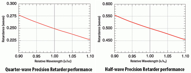
Sintec Optronics specializes in precision polymer retarders for the visible to near infrared region. Our Precision Retarders have the highest optical quality and tightest retardance tolerance of all polymer retarders. These true zero-order Precision Retarders consist of a birefringent polymer cemented between two precision polished, optically flat BK 7 windows. The retarder fast axis is conveniently marked for quick and easy reference. Precision Retarders are supplied with a broadband antireflection coating. Optical transmittance of a Precision Retarder is typically greater than 97%. The retardance at a wavelength λ that is different from the center wavelength λc is given by: δ ˜ δc(λc /λ) where δc is the retardance at λc. This relationship is very important when using sources which vary in wavelength from their nominal value. The 2 graphs show the retardance behavior as a function of relative wavelength for a quarter- and half-wave retarder, respectively. The Mueller calculus can be used to calculate the transmitted polarization state based upon the retardance differences from the ideal case. Since polymer retarders are true zero-order devices, they offer the significant advantage of improved angular performance. You can expect less than 1% retardance change over ±10° incidence angle. Sintec Optronics has developed precision ellipsometric techniques that can measure retardance to λ/1000.Our metrology for these measurements is the best in the industry. You can have absolute confidence that the calibration measurements supplied with your retarder are of the highest accuracy obtainable.
Features:
True zero-order retarders
Excellent off-axis performance
Unequaled measured accuracy
Less temperature dependence than quartz waveplates
Lower cost than compound zero-order quartz waveplates
Better angular acceptance than compound zero-order quartz waveplates
Technical specifications:
| Retarder Material | Birefringent Polymer |
| Substrate Material | N-BK7 |
| Stardard Wavelengths | 532, 632.8, 670, 780, 850, 1064, and 1550 nm |
| Custom Wavelengths | 400-1800 nm (specify) |
| Standard Retardances | λ/2 and λ/4 |
| Retardance Accuracy | ≤ λ/350 |
| Retardance Change (at 30˚tilt) | ≤ λ/40 and ≤ λ/80 |
| Transmitted Wavefront Distortion | ≤ λ/5 |
| Surface Quality (scratch-dig) | 40 -20 |
| Beam Deviation | ≤ 1 arc-min |
| Reflectance (per surface) | ≤ 0.5% at normal incidence |
| Threshold | 500 W/cm2, CW; 600 mJ/cm2, 20 ns, visible; 4 J/cm2, 20 ns, 1064 nm |
| Operating Temperature Range | -20˚C to -50˚C |
| Mounted | |||
| Clear Aperture in. [mm] | Dimensions ± 0.005 in. [ ± 0.13 mm] | Thickness ± 0.020 in. [ ±0.51 mm] | Part Number |
| Half Wave | |||
| 0.4 | Ø1.00 | 0.25 | STM-NHM-050-λ |
| [10.2] | [Ø25.4] | [6.35] | |
| 0.7 | Ø1.00 | 0.35 | STM-NHM-100-λ |
| [17.8] | [Ø25.4] | [8.9] | |
| 1.2 | Ø2.00 | 0.5 | STM-NHM-200-λ |
| [30.5] | [Ø50.8] | [12.7] | |
| Quarter Wave | |||
| 0.4 | Ø1.00 | 0.25 | STM-NQM-050-λ |
| [10.2] | [Ø25.4] | [6.35] | |
| 0.7 | Ø1.00 | 0.35 | STM-NQM-100-λ |
| [17.8] | [Ø25.4] | [8.9] | |
| 1.2 | Ø2.00 | 0.5 | STM-NQM-200-λ |
| [30.5] | [Ø50.8] | [12.7] | |
| Unmounted | |||
| Clear Aperture in. [mm] | Dimensions +0/-0.010 in. [+0/-0.25 mm] | Thickness ± 0.020 in. [± 0.51 mm] | Part Number |
| Half wave | |||
| 0.4 | Ø0.50 | 0.13 | STM-NH-050-λ |
| [10.2] | [Ø12.70] | [3.3] | |
| 0.8 | Ø1.00 | 0.26 | STM-NH-100-λ |
| [20.3] | [Ø25.4] | [6.3] | |
| 1.6 | Ø2.00 | 0.51 | STM-NH-200-λ |
| [40.6] | [Ø50.8] | [13.0] | |
| Quarter wave | |||
| 0.4 | Ø0.50 | 0.13 | STM-NQ-050-λ |
| [10.2] | [Ø12.70] | [3.3] | |
| 0.8 | Ø1.00 | 0.26 | STM-NQ-100-λ |
| [20.3] | [Ø25.4] | [6.3] | |
| 1.6 | Ø2.00 | 0.51 | STM-NQ-200-λ |
| [40.6] | [Ø50.8] | [13.0] | |
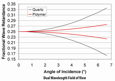
Dual wavelength retarders can provide the same retardance at two wavelengths that are separated in wavelength by more than the span covered by an achromatic retarder. They can also provide different specified retardances at two different wavelengths. Traditionally these retarders have been made using crystal quartz and are multiorder retarders at both wavelengths. Our dual wavelength retarders use polymers instead. They are usually much lower order and consequently have a slower change in retardance with angle of incidence as shown in the graph. On average the order is about 20% of that for a comparable quartz dual wavelength retarder. Call for a quote on a custom coating on these normally uncoated retarders. The retardance tolerance is ±0.01waves at both wavelengths. Many custom combinations not listed in the catalog are available. Please call for a quote on your custom requirement. Standard unmounted sizes are 0.50 inches and 1.00 inches.
Features:
Low order
Wide angular field
Broad wavelength coverage
Technical specifications:
| Retarder Material | Birefringent Polymer |
| Substrate Material | N-BK7 |
| Retardance Accuracy | ≤ λ/100 at both wavelengths |
| Transmitted Wavefront Distortion | ≤ λ/4 |
| Beam Deviation | ≤ 1 arc-min |
| Reflectance (per surface) | ~ 4% at normal incidence |
| Storage Temperature | design dependent |
| Operating Temperature | design dependent |
| Thickness in. [mm] | Dimensions in. [mm] | Part Number |
| 0.14 [3.6] | 0.50 [Ø12.7] | STM-D R1 R2-d-λ1/λ2 |
| 0.27 [6.9] | 1.00 [Ø25.4] | STM-D R1 R2-d-λ1/λ2 |
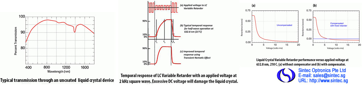
To prevent ionic buildup, which can damage the liquid crystal layer, liquid crystal devices should be electrically driven with an AC waveform with little to no DC component. We require a 2 kHz square wave of adjustable amplitude for controlling our Liquid Crystal Variable Retarders (LCVRs). Our Basic Controller and Four Channel Interface ensure these drive requirements are met. A temperature sensing and control option can be added to our LCVRs for accurate control of the operating temperature. A temperature sensor is attached directly to the LCVR substrate, outside its clear aperture and a heater is attached to the LCVR housing. This provides active heating and passive cooling of the liquid crystal device.
Features:
Computer control capability
Temperature control options
Usable from 450 to 1800 nm
Precision non-mechanical retardation control
Technical specifications:
| Retarder Material | Nematic liquid crystal |
| Substrate Material | Optical quality synthetic fused silica |
| Wavelength Range | 450-1800 nm (specify) |
| Retardance Range | |
| Without compensator | ~30 nm to λ/2 |
| With compensator | 0 to λ/2 |
| Transmitted Wavefront Distortion | ≤ λ/4 |
| Surface Quality (scratch-dig) | 40-20 |
| Beam Deviation | ≤ 2 arc min |
| Reflectance (per surface) | ≤ 0.5% at normal incidence |
| Temperature | 0˚C to +50˚C |
| Laser Damage Threshold | 500 W/cm2, CW; 300 mJ/cm2, 10 ns, visible |
| Clear Aperture in. [mm] | Diameter ± 0.005 in. [± 0.13 mm] | Thickness in. [mm] | Part Number |
| Without Attached Compensator (30 nm to λ/2) | |||
| 0.37 | Ø1.00 | 1.23 | STM-LVR-100 |
| [9.4] | [Ø25.4] | [31.2] | |
| 0.7 | Ø2.00 | 0.75 | STM-LVR-200 |
| [17.8] | [Ø50.8] | [19.1] | |
| 1.6 | Ø3.00 | 1 | STM-LVR-300 |
| [40.6] | [Ø76.2] | [25.4] | |
| With Attached Compensator (0 nm to λ/2) | |||
| 0.37 | Ø1.00 | 1.23 | STM-LRC-100 |
| [9.4] | [Ø25.4] | [31.2] | |
| 0.7 | Ø2.00 | 0.75 | STM-LRC-200 |
| [17.8] | [Ø50.8] | [19.1] | |
| 1.6 | Ø3.00 | 1 | STM-LRC-300 |
| [40.6] | [Ø76.2] | [25.4] | |
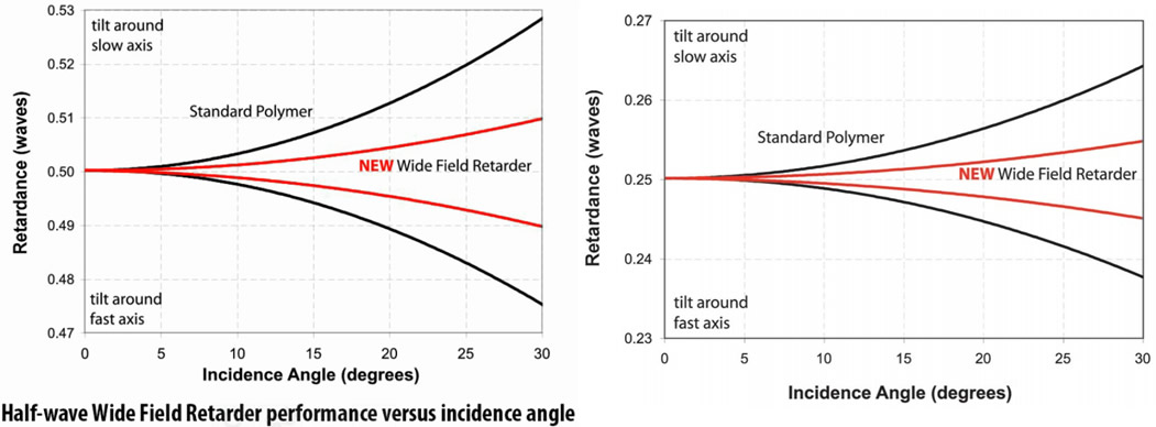
Sintec Optronics now offers Wide Field Retarders, the latest innovation in near zero-order polymer retarder technology. At their design wavelength, Wide Field Retarders provide a consistent retardance value over a wide acceptance angle, out to 30° or more. Standard quarter- and half-wave designs are available for common wavelengths in the visible to near infrared region. The graphs show the Wide Field Retarder performance as a function of incidence angle for the both half-wave and quarter-wave designs. Multilayer broadband antireflection (BBAR) coatings are included as standard. Note that BBAR coating performance varies with incidence angle; these coatings perform best at (or near) normal incidence. As with all Sintec Optronics retarders, the fast axis is conveniently marked. Custom retardance values are available for wavelengths from 400-1800 nm. Please call for application assistance or to request a custom quotation.
Features:
Unmatched off-axis performance
Standard and custom wavelength retarders
Mounted and unmounted versions available
Off-axis performance ideal for uncollimated light applications
Technical specifications:
| Retarder Material | Birefringent Polymer |
| Substrate Material | N-BK7 |
| Standard Wavelengths | 532, 632.8, 670, 780, 850, 1064, and 1550 nm |
| Custom Wavelengths | 400-1800nm (specify) |
| Retardance | λ/2 and λ/4 |
| Retardance Accuracy | ≤ λ/250 at normal incidence at the center of the part |
| Retardance Change (at 30˚tilt) | |
| Half-wave | ≤ λ/100 |
| Quarter-wave | ≤ λ/200 |
| Transmitted Wavefront Distortion | ≤ λ/2 |
| Surface Quality (scratch-dig) | 60-40 |
| Beam Deviation | ≤ 1 arc-min |
| Reflectance (per surface) | |
| At normal incidence | ≤ 0.5% |
| At 30˚ incidence | ≤ 1.0% |
| Operating Temperature | 0˚C to 40˚C |
Sintec Optronics is pleased to present our Bare Polymer Retarder film. Our proprietary polymer film provides high retardance accuracy in a cost effective product which can be provided in almost any configuration and quantity. The temperature dependence of the nominal retardance is approximately 0.01%/°C, which provides a very stable and versatile polarization solution. Manufactured in-house for wavelengths between 400 and 1800nm, this retarder is ideal for applications requiring a high precision, thin and cost effective solution. We are also able to tune the retardance to your Angle of Incidence to optimize performance. AR coatings are available on a special order basis. Standard shapes and retardance values are available when quick turn-around is needed. We can also accommodate requests for custom shapes, sizes (up to 4 inches) and retardance values.
Features:
Very thin profile
Thermally stable
High volume scalable
AR coatings available
Custom retardance available
Technical specifications:
| Substrate Material | Polymer Film |
| Thickness | 0.005 inch (127 µm), nominal |
| Wavelength Range | 400-1800 nm |
| Retardance Ranges | Single Layer: 20-1600 nm |
| Double Layer: 1600-3000 nm | |
| Reflectance | ~4% per surface |
| Retardance Variation | ≤ 2%/in. |
| Retardance Accuracy | ± λ/300 |
| Acceptance Angle | ± 6˚ |
| Transmitted Wavefront Distortion | ≤ 2λ (P-V @ 633) |
| [≤ λ/2 (RMS @ 633)] | |
| Surface Quality | 80-50 scratch-dig |
| Beam Deviation | ≤ 30 arc-sec |
| Operating Temperature | -40˚C to +60˚ C |
| Round | |||
| Clear Aperture (in.) | Thickness (in.) | Dimensions (in.) | Part Number |
| 0.45 | 0.01 | Ø0.50 | λ/4 Wave: STM-BQ-050-λ |
| λ/2 Wave: STM-BH-050-λ | |||
| 0.9 | 0.01 | Ø1.00 | λ/4 Wave: STM-BQ-100-λ |
| λ/2 Wave: STM-BH-100-λ | |||
| 1.35 | 0.01 | Ø1.50 | λ/4 Wave: STM-BQ-150-λ |
| λ/2 Wave: STM-BH-150-λ | |||
| 1.8 | 0.01 | Ø2.00 | λ/4 Wave: STM-BQ-200-λ |
| λ/2 Wave: STM-BH-200-λ | |||
| Square | |||
| 0.45 x 0.45 | 0.01 | 0.50 x 0.50 | λ/4 Wave: STM-BQ-050x050-λ |
| λ/2 Wave: STM-BH-050x050-λ | |||
| 0.90 x 0.90 | 0.01 | 1.00 x 1.00 | λ/4 Wave: STM-BQ-100x100-λ |
| λ/2 Wave: STM-BH-100x100-λ | |||
| 1.35 x 1.35 | 0.01 | 1.50 x 1.50 | λ/4 Wave: STM-BQ-150x150-λ |
| λ/2 Wave: STM-BH-150x150-λ | |||
| 1.80 x 1.80 | 0.01 | 2.00 x 2.00 | λ/4 Wave: STM-BQ-200x200-λ |
| λ/2 Wave: STM-BH-200x200-λ | |||
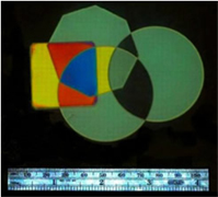
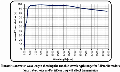
Retarder Applied Polymer (RAPtor) parts are manufactured using a proprietary high birefringent polymer. These retarders are true zero order with a typical film thickness less than 10 microns. The material can be added to customer provided windows and even mildly curved substrates to produce truly custom solutions. These retarders were originally designed for use in astronomy but have applications wherever a true zero order waveplate would be used. Sintec Optronics can apply these retarders to substrates from 10 mm to 100 mm diameter (and even larger on a custom basis).
Features:
Extremely thin and large diameter
Curved surfaces
High temperature resistance
Custom sizes, shapes, wavelengths and retardances available
Technical specifications:
| Retarder Material | High Birefringence Polymer |
| Retarder Thickness | < 10 µm** |
| Substrate Material | 1.1 mm Fused Silica |
| Wavelength Range/Retardance | 400 - 1064 nm ( λ/2 ) |
| 400 - 1550 nm ( λ/4 ) | |
| Retardance Accuracy | < ± λ/100 |
| Retardance Uniformity | < λ/100 [<5 nm] |
| Clear Aperture | 80% |
| Reflectivity | ≤ 0.5% |
| Transmitted Wavefront Distortion | ≤ λ/2 (P-V @ 633 nm) |
| [≤ λ/8 (RMS @ 633 nm)] | |
| Beam Deviation | ≤ 5 arc sec |
| Surface Quality | 80-50 scratch-dig |
| Operating Temperature | -20 °C to 80 °C |
| Storage Temperature | -40 °C to 80 °C |
| Custom Design | |
| Wavelength Range | 350-3300 nm |
| Retardance Accuracy | < ± λ/200 |
| Dimensions | up to 150 mm diameter |
| Fast Axis Datum/Orientation | Customer specified |
| Substrate Material/Geometry/Thickness | Customer specified |
| Clear Aperture in. [mm] | Diameter in. [mm] | Part Number |
| Ø0.9 in. [22.9 mm] | Ø1.00 in. [25.4 mm] | STM-PQ-100-λ , STM-PPH-100-λ |
| Ø1.8 in. [45.7 mm] | Ø2.00 in. [50.8 mm] | STM-PPQ-200-λ , STM-PPH-200-λ |
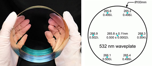
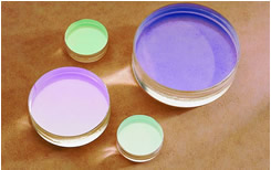
For many astronomical, aerospace, and defense projects, large aperture retarders are required. Sintec Optronics has over thirty-five years of retarder manufacturing expertise and is able to manufacture from a wide variety of materials to facilitate high or low power applications. Waveplates up to 150 mm diameter are available. Some materials allow retarders to be used over different wavelengths from the ultraviolet, through the visible and into the near infrared. Sintec Optronics uses proprietary methods to ensure the best spatial uniformity of its polymer and crystalline retarders. These retarders have a spatial uniformity of better than two percent across the clear aperture and with the correct substrates, can have a wavefront distortion that is on par with Meadowlark Optics’ Precision Retarders.
Features:
Outer diameter up to 6 inches
Clear aperture > 90%
Custom size, retardance and wavelength range available
Spatial uniformity of less than 2% across clear aperture
Various materials available: (polymer, quartz, sapphire, magnesium fluoride and liquid crystal)
Technical specifications:
| Retarder (Bifringent) Material Options | Polymer |
| Crystalline Quartz | |
| Magnesium Fluoride | |
| Sapphire | |
| Liquid Crystal† | |
| Wavelength | 300-2500 nm (specify) |
| Retardances | 0 to 100s of λ |
| Retardance Accuracy | |
| Center | ≤ λ/100 to ≤ λ/350 |
| Spatial Uniformity | ≤ λ/10 to ≤ λ/100 |
| Transmitted Wavefront Distortion | ≤ λ to ≤ λ/5 (P-V @ 633) |
| [ λ/4 to λ/20 (RMS @ 633)] | |
| Surface Quality | 40-20 scratch-dig to 80-50 scratch-dig |
| Outside Dimensions | up to 150 mm |
Sintec Optronics is pleased to offer a selection of quarter- and half-wave achromatic retarders that span the UV, visible, near IR and IR portions of the spectrum. Two multi-order crystalline retarders, one made of crystalline quartz and the other magnesium fluoride, are combined in a subtractive mode to give an effective zero-order waveplate. By a careful choice of waveplate thicknesses, retardance dispersion is balanced to give a nearly constant retardance (in waves) over a broad range of wavelengths. The useable wavelength range is defined to give a retardance value within λ/100 of the nominal value. Custom designs with larger achromatic ranges or deeper UV wavelengths are available on request. Bi-Crystalline Achromats are similar in achromatic performance to our polymer achromats in the visible, but they excel in the IR. They have higher power handling capability than our polymer achromats and can with stand higher storage temperatures. Their field of view is narrow compared to polymer achromats. Typically, they cannot be expected to meet their retardance accuracy for rays whose incidence angles exceed 1.5°. If you must have the performance of a Bi-Crystalline Achromat and a large field of view, call us. We have a proprietary design that can be your polarization solution.
Features:
High Damage Threshold
Volume Pricing
Superior IR performance
Technical specifications:
| Retarder Material | Quartz & Magnesium Fluoride |
| Retardance Accuracy | λ/4 or λ/2 |
| Temp. Coefficient of Retardance | λ/500 per ˚C |
| Standard Wavelengths - Quarter Wave | |
| Ultraviolet | 395-465 nm |
| Visible | 475-590 nm |
| Near Infrared | 600-900 nm |
| Infrared | 690-2050 nm |
| Standard Wavelengths - Half Wave | |
| Ultraviolet | 412-475 nm |
| Visible | 500-650 nm |
| Near Infrared | 600-840 nm |
| Infrared | 1190-1660 nm |
| Transmitted Wavefront Distortion | ≤ λ/4 |
| Surface Quality (scratch-dig) | 40-20 |
| Beam Deviation | ≤ 1 arc-min |
| Reflectance (per surface) | ≤ 0.5% at normal incidence |
| Storage Temperature | -40˚C to +75˚C |
| Threshold | 2 J/cm2, 10 ns, 1064 nm |
| Mounted | ||
| Clear Aperture in. [mm] | Diameter in. [mm] | Part Number |
| Half Wave | ||
| 0.4 | Ø1.00 | STM-CHM-050 |
| [10.2] | [Ø25.4] | |
| Quarter Wave | ||
| 0.4 | Ø1.00 | STM-CQM-050 |
| [10.2] | [Ø25.4] | |
| Unmounted | ||
| Clear Aperture in. [mm] | Diameter in. [mm] | Part Number |
| Half Wave | ||
| 0.4 | Ø0.50 | STM-CH-050 |
| [10.2] | [Ø12.7] | |
| Quarter Wave | ||
| 0.4 | Ø0.50 | STM-CQ-050 |
| [10.2] | [Ø12.7] | |
A leading supplier and manufacturer of a wide range of photonics products such as lasers,laser parts & machines.
Office: 10 Bukit Batok Crescent #07-02 The Spire Singapore 658079
Tel: +65 63167112
Fax: +65 63167113
Whatsapp: +65 91904616