 English
 Français
 Deutsch
 euskara
 Русский язык
 Italiano
 Português
 Nederlands
 Polski
 Greek
Greek Lietuva
 Türkçe
 日本語
日本語 한어
한어 中文
中文 தாமில்
 فارسی
فارسی हिंदी
हिंदी Tiếng Việt
 ภาษาไทย
 Pilipino
 Indonesia
 தாமில்
Send us a message
CLOSE
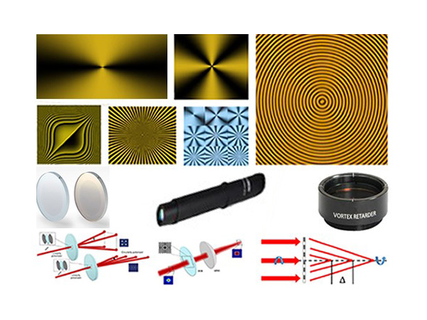


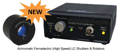
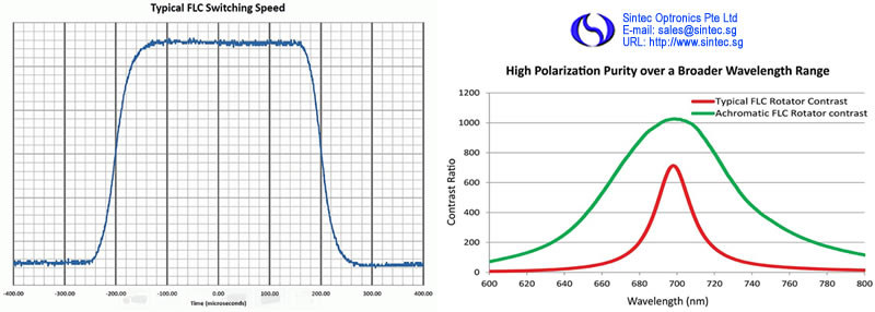
Sintec Optronics’ Ferroelectric Liquid Crystal (FLC) devices offer a significant performance advantage in optical shutter and rotator applications demanding the fastest optical response times available. FLC devices are designed for applications requiring active timing control of beam transmittance. Key features of our FLC devices include high-speed binary operation, high purity linear polarized output, and maximum extinction ratio performance. Since these devices are solid state – undesirable mechanical motion, associated noise, and vibration problems are eliminated. Our FLC devices require a DC-balanced AC drive signal, typically resulting in a 50% duty cycle operation. Our optional FC 5010 Controller is ideal for driving the devices for optimal performance (sold separately).
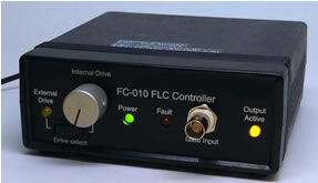
FLC Controller (FCS010)
The FCS010 is a two-channel liquid crystal controller specifically designed to drive our ferroelectric liquid crystal shutters and rotators. The FCS010 has two short-circuit protected output channels driven 180 degrees out of phase. The pre-configured controller waveforms are optimized for FLC devices. We can tailor the waveform to your specific needs based on application and purchased FLC device. The drive waveform is output through SMA connectors. The controller is 100% RoHS compliant and is powered by a separate 12V international power supply.
Features:
Mounted and unmounted design options
Extremely fast switching speeds
Silent, vibration-free
Low-voltage operation
OEM sizes and shapes
No mechanical motion
Stand alone controller available
Optimized waveforms for driving FLC devices
Technical specifications:
Achromatic FLC Rotator:
| Retarder Material | Ferroelectric liquid crystal |
| Substrate Material | Fused silica |
| Wavelength Range | 405-850 nm, custom ranges up to 2 microns |
| Transmitted Wavelength Distortion | λ/2 (P-V @ 633), [λ/10 (RMS @ 633)] |
| Surface Quality | 60-40 scratch dig |
| Beam Deviation | ≤ 5 arc min |
| Outside Diameter (mounted) | 2.00 ± 0.005 in. please inquire about custom sizes |
| Clear Aperture | 0.70 in. |
| Response Time (10-90% & 90-10%) | ≤ 100 micro-sec at room temp, wavelength dependent |
| Operating Temperature | 20°C to 30°C |
| Storage Temperature | 0°C to 60°C |
| Driver Requirements | ± 5 to 30 Volts, 50% duty cycle |
Achromatic FLC Shutter:
| Polarizer Material | Dichroic Polymer |
| Transmission | ≥ 30% (typical - unpolarized light) |
| ≥ 65% (typical - polarized light) | |
| Wavelength Range | 450-720 nm, custom ranges up to 2 microns |
| Transmitted Wavefront Distortion | λ/2 (P-V @ 633), [λ/8 (RMS @ 633)] |
| Contrast Ratio | ≥ 200:1 |
Achromatic FLC Controller:
| Dimensions | 5.3 in. W x 5.3 in. L x 2.0 in. H, (13.5 cm W x 13.5 cm L x 5.1 cm H) |
| Number of LC Channels | Two, running identical programs 180, degrees out of phase |
| Output Waveform | Bipolar ± 15V peak voltage, ± 10V holding voltage |
| Amplitude Resolution | 16-bit; 1 mV voltage resolution |
| Internal Drive | 1 to 10,000 Hz, 50% duty cycle, frequency controlled by front-panel, 10-turn knob |
| Product Description | Diameter (in.) | Clear Aperture (in.) | Thickness (in.) | Part Number |
| Rotator | 2.00 [50.8 mm] | 0.70 [17.78 mm] | 1.38 [19.05 mm] | STM-FPA-200-λ |
| Shutter | 1.00 [25.4 mm] | 0.37 [9.4 mm] | 1.42 [36.07 mm] | STM-FCS-100-λ |
| 2.00 [50.8 mm] | 0.70 [17.78 mm] | 1.13 [28.7 mm] | STM-FCS-200-λ | |
| Controller | N/A | N/A | N/A | STM-FC010 |
Sintec Optronics is pleased to announce a small, mounted liquid crystal family of products intended for space constrained or OEM applications. By removing the temperature control circuitry, the overall dimensions of the housing can be significantly reduced. For even tighter mechanical constraints, unmounted cells are also available with flying leads or custom connectors.
Features:
Precision control at lower cost
Scalable quantities
Thin housing
Large clear aperture
Usable from 450 to 1800 nm
Technical specifications:
| Retarder Material | Nematic liquid crystal |
| Substrate Material | Optical quality synthetic fused silica |
| Wavelength Range | 450 - 1800 nm (specify) |
| Retardance Range | ~30 nm to λ/2, custom ranges are available |
| Transmitted Wavefront Distortion | λ/2 (P‐V @ 633), [λ/8 (RMS @ 633)] |
| Surface Quality | 80 - 50 scratch-dig |
| Beam Deviation | 3 arc min |
| Reflectance (per surface) | 0.5% at normal incidence |
| Diameter Tolerance | ± 0.005 in. |
| Temperature Range | 0°C to 50°C |
| Laser Damage Threshold | 500 W/cm2, CW; 300 mJ/cm2, 10 ns, visible |
| Clear Aperture in. [mm] | Thickness in. [mm] | Diameter in. [mm] | Part Number |
| 0.49 [12.5] | 0.25 [6.35] | Ø1.00 [Ø25.4] | STM-LVT-100 |
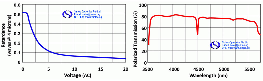
Liquid crystal technology for polarization control now extends into the mid IR. Sintec Optronics standard line of polarization controllers can be used for these new variable retarders. They can be custom configured for use as variable attenuators and as polarization rotators.
Features:
3600 to 5500 nm transmission
Non-mechanical polarization control
Computer controllable
Useful for variable attenuation
Technical specifications:
| Retarder Material | Nematic liquid crystal |
| Substrate Material | Anti-reflection coated germanium |
| Wavelength Range | 3.6 µm to 5.7 µm |
| Maximum Retardance | 1/2 λ at 4 µm* |
| Minimum Retardance | 0.06 λ at 4 µm at 10 V |
| Reflectance | ≤ 5% per external surface |
| Operating Temperature Range | 0˚C to +50˚C |
| Response Times | < 500 msec |
| Clear Aperture in. [mm] | Diameter ± 0.005 in. [± 0.13 mm] | Thickness in. [mm] | Part Number |
| 0.7 [17.8] | Ø2.00 [Ø50.8] | 0.75 [19.1] | STM-LVR-200-λ |
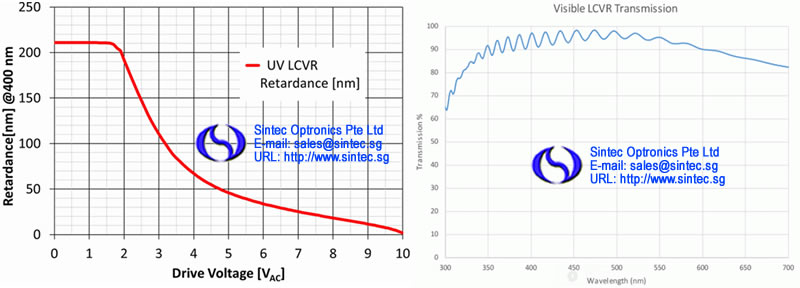
Liquid crystal technology for polarization control now extends into the ultraviolet. While standard LC materials are susceptible to UV light damage below 450 nm, Sintec Optronics has designed a new UV-resistant LCVR material capable of operating at lower wavelengths (as low as 350 nm). These parts can be custom configured for use as variable attenuators or polarization rotators and are compatible with our standard line of liquid crystal controllers.
Features:
Phase of Amplitude modulation of UV spectrum
Analog modulation
Non-mechanical polarization control
Low absorption
High UV tolerance LC
Technical specifications:
| Retarder Material | Nematic liquid crystal |
| Substrate Material | UV Grade Fused Silica |
| Wavelength Range | 350-450 nm (specify) |
| Maximum Retardance* | 1/2 λ at 400 nm |
| Minimum Retardance | 0.06 λ at 400 nm (at 10 V) |
| Transmitted Wavefront Distortion | λ/4 (P-V @ 633), [λ/16 (RMS @ 633)] |
| Surface Quality | 40-20 scratch-dig |
| Beam Deviation | 2 arc min |
| Reflectance* | AR coatings are available |
| Diameter Tolerance | ± 0.010 in. |
| Temperature Range | 0˚C to +50˚C (Operating) |
| Clear Aperture in. [mm] | Thickness in. [mm] | Diameter in. [mm] | Part Number |
| 0.37 [9.4] | 1.23 [31.2] | Ø1.00 [Ø25.4] | STM-LVR-100-UV |
| 0.7 [17.78] | 0.75 [19.05] | Ø2.00 [Ø50.8] | STM-LVR-200-UV |
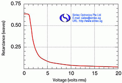
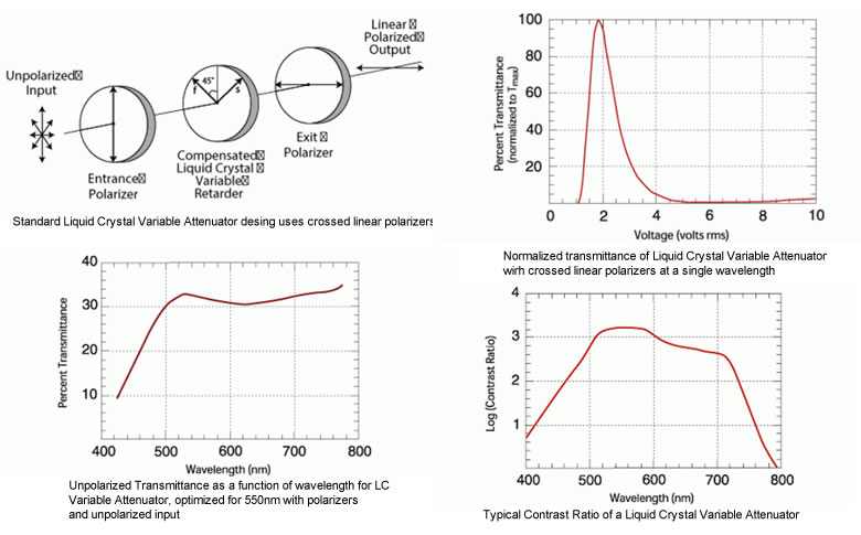
Sintec Optronics’ Liquid Crystal Variable Attenuator (LCVA) offers real-time, continuous control of light intensity. Our attenuator consists of an LC Variable Retarder (with attached compensator) operating between crossed linear polarizers. With crossed polarizers, light transmission is maximized by applying the correct voltage to achieve half-wave retardance from the LC cell as shown in figure 4-11. Half-wave operation rotates the incoming polarization direction by 90°, so that light is passed by the second polarizer. Minimum transmission is obtained with the retarder operating at zero (or a whole number of) waves. Transmission decreases as the applied AC voltage amplitude increases (half- to zero-waves retardance). The relationship between transmittance T and retardance (in degrees) for crossed polarizer configuration is given by: T(Θ) = 1/2 [1 - cos(Θ)] Tmax where Tmax is the maximum transmittance when retardance is exactly one-half wave (or 180°). Figure 4-12 shows transmittance as a function of applied voltage. Maximum transmission is dependent upon properties of the LC Variable Retarder as well as the polarizers used in your system. Figure 4-13 shows the transmission of an LC Variable Attenuator optimized for use at 550 nm with crossed polarizers. An unpolarized light source is used for illumination. Extinction ratio is defined as the maximum transmission (LC cell at half-wave) pided by the minimum transmission (LC cell at zero waves). Values exceeding 1000:1 (see figure 4-14) can be obtained for a single wavelength by optimizing the applied voltage levels for minimum and maximum transmission. We guarantee a minimum extinction ratio of 500:1 at your specified wavelength. A Liquid Crystal Variable Attenuator can be configured with high efficiency calcite or beamsplitting polarizers to maximize light transmittance and increase damage threshold. With a linearly polarized input beam and a calcite polarizer, transmittance values exceed 90% at most wavelengths. Very high extinction ratios, in excess of 5000:1, can be achieved with custom double attenuators. In this design, two Liquid Crystal Variable Retarders are combined with three polarizers.
Features:
High contrast ratio
Computer control capabilities
Continuous control of light intensity
Technical specifications:
| Retarder Material | Nematic liquid crystal with Birefringent polymer |
| Polarizer Material | Dichroic polymer |
| Substrate Material | Optical quality synthetic fused silica |
| Wavelength Range | |
| Visible | 450-700 nm |
| Near Infrared 1 | 650-950 nm |
| Near Infrared 2 | 900-1250 nm |
| Near Infrared 3 | 1200-1700 nm |
| Contrast Ratio | 500:1 at single wavelength |
| Transmitted Wavefront Distortion | ≤ λ/4 (each component) |
| Surface Quality (scratch-dig) | 40-20 |
| Beam Deviation | ≤ 2 arc min |
| Reflectance (per surface) | ≤ 0.5% at normal incidence |
| Operating Temperature | 0˚C to 50˚C |
| Laser Damage Threshold | 1 W/cm2, CW (dichroic polarizers) |
| Clear Aperture in. [mm] | Diameter ± 0.005 in. [± 0.13 mm] | Thickness in. [mm] | Part Number |
| 0.37 | Ø1.00 | 1.23 | STM-LVA-100-λ |
| [9.4] | [Ø25.4] | [31.2] | |
| 0.7 | Ø2.00 | 0.75 | STM-LVA-200-λ |
| [17.8] | [Ø50.8] | [19.1] | |
| 1.6 | Ø3.00 | 1 | STM-LVA-300-λ |
| [40.6] | [Ø76.2] | [25.4] |
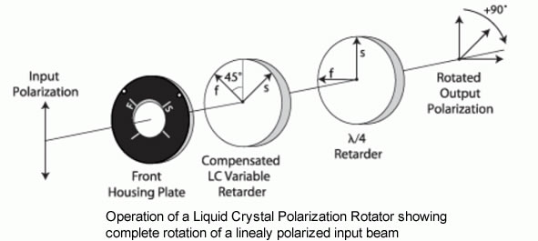
Our Liquid Crystal Polarization Rotator (LPR) continuously rotates the polarization orientation of a monochromatic, linearly polarized input beam. Our LPR consists of a compensated Liquid Crystal Variable Retarder combined with a zero-order polymer quarter-wave retarder. The fast axis of the liquid crystal variable retarder is oriented at 45° to the slow axis of the quarter-wave retarder and the linearly polarized input must be parallel to the quarter-wave retarder slow axis. Polarization rotation is achieved by electrically controlling the retardance of the Liquid Crystal Variable Retarder, eliminating any mechanical motion. A quarter-wave retarder converts elliptical polarization formed by the Liquid Crystal Variable Retarder to linear polarization. The rotation angle is equal to one-half the retardance change from the Liquid Crystal Variable Retarder. Response time of the LPR depends upon the desired amount of rotation. Small rotations have a longer response time because of a smaller change in the electric field strength. Polarization purity is defined as the ratio of the rotated linear component to the orthogonal component and, on average, polarization purity (or extinction ratio) is better than 150:1. We provide test data including the required voltages corresponding to polarization orientations, in 10° increments, from approximately -40° to approximately 140° rotation. These measurements are taken at ambient temperature for your specified wavelength. Standard Liquid Crystal Polarization Rotators are supplied without an input polarizer. Input polarization direction must be precisely aligned for optimum performance.
Features:
High power capability
High polarization purity
Computer control capability
180 degree polarization rotation
Continuous rotation of linearly polarized light
Technical specifications:
| Retarder Material | Nematic liquid crystal with Birefringent polymer |
| Substrate Material | Optical quality synthetic fused silica |
| Wavelength | 450 -1800 nm (specify) |
| Polarization Rotation | 180˚ |
| Polarization Purity | 150:1 average |
| Transmittance | > 92% with polarized input |
| Transmitted Wavefront Distortion | n ≤ λ/4 |
| Surface Quality (scratch-dig) | 40-20 |
| Beam Deviation | ≤ 2 arc-min |
| Reflectance (per surface) | ≤ 0.5% at normal incidence |
| Operating Temperature | 0˚C to +50˚C |
| Laser Damage Threshold | 500 W/cm2, CW; 300 mJ/cm2, 10 ns, visible |
| Clear Aperture in. [mm] | Diameter ± 0.005 in. [± 0.13 mm] | Thickness in. [mm] | Part Number |
| 0.37 | Ø1.00 | 1.23 | STM-LPR-100-λ |
| [9.4] | [Ø25.4] | [31.2] | |
| 0.7 | Ø2.00 | 0.75 | STM-LPR-200-λ |
| [17.8] | [Ø50.8] | [19.1] | |
| 1.6 | Ø3.00 | 1 | STM-LPR-300-λ |
| [40.6] | [Ø76.2] | [25.4] |
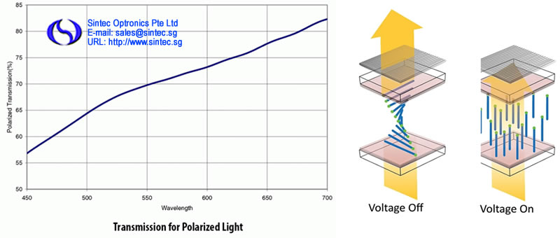
Our liquid crystal shutter uses twisted nematic liquid crystals to provide a vibration-free mechanical shutter alternative. The twisted nematic liquid crystal switches between a state that rotates the input polarization by 90° with no voltage applied and a state that makes no change in the input polarization with 8 to 10 volts applied. The applied voltage is a 2 kHz AC square-wave. The shutter is supplied with integral dichroic visible polarizers to provide an average extinction ratio of better than 1,000:1. Custom shutters with larger aperture sizes and with wavelength coverage to 2.1 microns are available on a custom basis.
Features:
High contrast
No mechanical motion
Computer control capacity
No vibration
Technical specifications:
| Liquid Crystal Configuation | Twisted nematic |
| Substrate Material | Optical quality synthetic fused silica |
| Polarizer Material | Dichroic polymer |
| Wavelength Range | 450-1800 nm |
| Contrast Ratio (average) | 1,000:1 |
| Acceptance Angle | 25˚ incidence angle with some reduction above 10˚ |
| Switching Time (10% to 90% at room temperature) | |
| Closed to open: | 5 milliseconds |
| Open to closed: | 0.4 milliseconds |
| Transmitted Wavefront Distortion | ≤ λ/2 |
| Surface Quality (scratch-dig) | 60-40 |
| Beam Deviation | ≤ 5 arc min |
| Reflectance (per surface) | ≤ 0.5% at normal incidence |
| Laser Damage Threshold | 1 W/cm2, CW |
| Glass Thickness | 0.48-0.52 in. |
| Polarization Direction | Vertical on input face, horizontal on output face |
| Storage Temperature | -20˚C to +80˚C |
| Operating Temperature | 0˚C to +50˚C |
| Clear Aperture in. [mm] | Diameter ± 0.005 in. [± 0.13 mm] | Thickness in. [mm] | Part Number |
| 0.37 | Ø1.00 | 1.23 | STM-LCS-100 |
| [9.4] | [Ø25.4] | [31.2] | |
| 0.7 | Ø2.00 | 0.75 | STM-LCS-200 |
| [17.8] | [Ø50.8] | [19.1] | |
| 1.6 | Ø3.00 | 1 | STM-LCS-300 |
| [40.6] | [Ø76.2] | [25.4] |
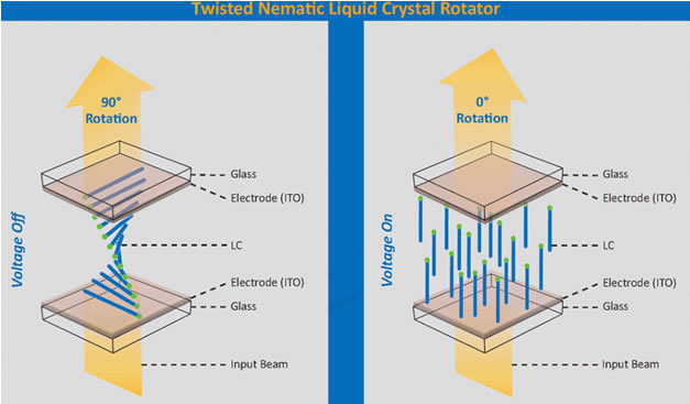
An Optical Rotator is a two-state device used to rapidly switch between two orthogonal sites of linear polarization. One state has output linear polarization parallel to an input linear polarization state. This occurs when voltage is applied to the rotator. The other state has output polarization orthogonal to the input polarization and occurs when no voltage is applied. Sintec Optronics manufactures and sells liquid crystal based Optical Rotators for applications requiring active timing control of beam transmittance by using them in combination with high quality polarizers. Key features of our Optical Rotators include high-speed binary operation, high purity linear polarized output, and maximum extinction ratio performance. Since these devices are solid state – undesirable mechanical motion, associated noise, and vibration problems are eliminated. Binary LC Rotators deliver optimum extinction ratio performance, often greater than 10,000:1 across the visible wavelength range, when used with high quality polarizers. Even higher extinction performance is achieved over narrower bandwidths or for single laser line applications. Up to 100% duty cycle operation is standard. This Rotator has a broad operating temperature range, designed to meet applications requiring low cost components with negligible impact on performance.
Features:
High polarization purity
Silent, vibration-free
Low-voltage operation
Broad thermal range
Faster switching speeds than LCVRs
Technical specifications:
| Retarder Material | Twisted Nematic liquid crystal |
| Substrate Material | Optical quality synthetic fused silica |
| Wavelength Range | 400 - 1800 nm |
| Transmitted Wavefront Distortion | λ/4 (P-V @ 633 nm), [λ/16 (RMS @ 633 nm)] |
| Response Time (VIS) | ≤ 5 ms |
| Surface Quality | 40-20 scratch-dig |
| Beam Deviation | 2 arc min |
| Reflectance (per surface) | 0.5% at normal incidence |
| Diameter Tolerance | ± 0.010 in. |
| Operating Temperature Range | 10°C to 60°C (Operating); -40°C to 90°C (Storage) |
| Laser Damage Threshold | 500 W/cm2, CW; 300 mJ/cm2, 10 ns, visible |
| Diameter (in.) | Clear Aperture (in.) | Thickness (in.) | Part Number |
| 1.00 [25.4 mm] | 0.37 [9.4 mm] | 1.23 [31.24 mm] | STM-LTN-100-λ |
| 2.00 [50.8 mm] | 0.70 [17.8 mm] | 0.75 [19.05 mm] | STM-LTN-200-λ |
| We offer Binary LC Rotators to cover four spectral regions: | |||
| VIS: 450 – 700 nm | |||
| IR 1: 650 – 950 nm | |||
| IR 2: 900 – 1250 nm | |||
| IR 3: 1200 – 1700 nm | |||
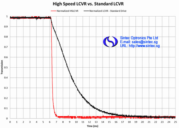
Sintec Optronics newest liquid crystal (LC) product, the high speed LC variable retarder (HS LCVR) has a 10X speed improvement over our award winning standard LCVR. The sub-millisecond speeds are achieved without the 50/50 duty cycle drive scheme required by our ferroelectric liquid crystal components, but are nearly as fast. The new LCVR uses nematic liquid crystal materials to electrically control polarization and provide tunable retardation by changing the effective birefringence of the material with applied voltage, thus altering the input polarized light to any chosen elliptical, linear or circular polarization. Our precision HS LCVR requires unique fabrication and assembly steps. We construct these retarders using optically flat fused silica windows coated with our transparent conductive Indium Tin Oxide (ITO). Our ITO coating is specially designed for maximum transmission from 400 – 700 nm. Liquid Crystal Variable Retarder response time depends on several parameters, including layer thickness, viscosity, temperature, variations in drive voltage and surface treatment. Liquid crystal response time is proportional to the square of the layer thickness and therefore, the square of the total retardance.
Features:
Sub-millisecond speeds
Standard LC Drive Schemes
Includes heated housing
Precision non-mechanical retardation control
Technical specifications:
| Retarder Material | Nematic liquid crystal |
| Substrate Material | Optical quality synthetic fused silica |
| Wavelength Range | 450 - 700 nm |
| Typical LC Rise Time (10 – 90%) | 50 µs @ 532 nm |
| Typical LC Fall Time (90 – 10%) | 500 µs @ 532 nm |
| Retardance | 0 to λ/2 |
| Transmitted Wavefront Distortion (at 632.8 nm) | ≤ λ/4 |
| Surface Quality | 40-20 scratch-dig |
| Beam Deviation | ≤ 2 arc min |
| Reflectance (per surface) | ≤ 0.5% at normal incidence |
| Temperature Range | 50°C |
| Recommended Safe Operating Limit | 500 W/cm 2, CW; 300 mJ/cm2, 10 ns, visible |
| Diameter, D (in.) | Clear Aperture, CA (in.) | Thickness, t (in.) | Part Number |
| 2 | 0.8 | 0.75 | STM-HSLRC-200 |
Sintec Optronics is excited to announce the release of the Model B1010, our new Analog Liquid Crystal Controller. This liquid crystal (LC) driver is designed to integrate with any single (standard) Meadowlark Optics LC device currently offered as well as any nematic Liquid Crystal device compatible with the specifications listed. Independent voltage settings allow easy and repeatable selection of two retardance values. Often, it is desirable to modulate between the two states. For example, switching between quarter-wave and three quarterwave retardance changes linearly polarized light between left and right circular. A manual toggle allows easy switching between two states. Banana jacks between the knobs allow for continuous voltage monitoring without interfering with LC device connections. Each Sintec Optronics Liquid Crystal Variable Retarder is supplied with a plot of its actual retardance versus voltage. Using your Model B1010 Controller and this retardance plot ensures accurate retardance to voltage correlation.
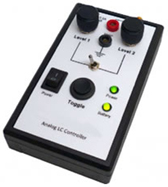
Features:
Convenient, stand-alone bench top operation
Versatile-compatible with all standard Sintec Optronics LC devices and other nematics
Out-of-the-box functionality. Sets up in minutes
Optional battery supply for short term use
Banana jacks allow for easy multimeter attachment
Technical specifications:
| Output Voltage | 0 to 20 VAC, RMS, maximum |
| Fundamental Drive Waveform | 2 kHz AC square wave |
| External Modulation (input) | none |
| Output Bias | ± 10 mV DC |
| Power Requirements | 12 VDC 200 mA or 9V battery external power supply included 100-240 VAC 50-60 Hz, 0.3 A International Plugs |
| Battery Life | 1 hour (intended for convenience, not as a primary power source) |
| External Dimensions (W x D x H) | 3.3 x 6.0 x 2.2 in. |
| Weight | < 1 lb. |
| CE Compliance | Compliant |
| Item | Part Number |
| Analog Liquid Crystal Controller | STM-B1010 |
| B1010 Package | |
| B1010 Controller Unit | |
| Power Supply | |
| SMA-BNC Adapter | |
| Internal Plug Set | |
| 9 Volt Battery | |
| User Manual | |
Our two Channel High Voltage Digital Interface is designed for independent high precision computer control of up to two Sintec Optronics Swift LC liquid crystal devices at one time. The D3060HV Package includes all the functionality of the D3050 plus the high voltage circuitry necessary for Swift LC devices. Also included is capability for temperature monitoring and control on one channel. The Advanced Package allows the amplitude of the 13 kHz square wave output to be driven either by an external signal supplied to a front panel connector or specific CellDRIVE generated waveforms including sinusoidal, square, triangle, sawtooth and transient nematic effect waveforms. Additional functions include the capability to output a sync pulse on a front panel connector at desired points in the CellDRIVE generated waveforms and the ability to save/restore all CellDRIVE settings to/from a file.
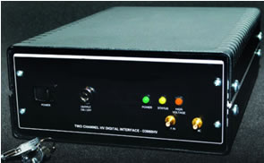
Features:
USB or RS232 interface
C++ code examples (all required libraries included)
Compact and simple to use
Microsoft® HyperTerminal configuration file included
Independent control of voltage levels on two channels to 10 mV resolution
Includes National Instruments LabVIEW™ Virtual Instrument drivers to interface with custom software
Technical specifications:
| Fundamental Drive Waveform | 13 kHz ac square wave |
| Modulation Amplitude | 0-100 V rms |
| Modulation Resolution | 10 mV (1.55 mV using LabVIEW™ subroutines) |
| DC Offset | < 50 mV |
| Communications Interface | USB or RS232 |
| LC Cell to Controller Connections | LEMO™ RF cable, 2 m length |
| Power Requirements | 100-240 V ac; 47-63 Hz; 2.5 A |
| Safety Feature | Keyed Interlock Switch |
| Modulation Waveforms | External modulation input (0-5 V) |
| Sinusoidal | |
| Triangle | |
| Square | |
| Sawtooth | |
| Transient nematic effect | |
| Temperature Control | Active heating/passive cooling to within ± 1˚C of nominal set point |
| Sync Output | TTL, 1 µs pulse, user specified phase |
| Minimum System Requirements | |
| USB or RS232 COM Port | |
| Use of LavVIEW Instrument Library requires LabVIEW version 2010 or higher | |
| Item | Part Number |
| High Voltage Controller | STM-D3060HV |
| High Voltage Cable | Swift LC Cable |
The new D5020 Liquid Crystal Digital Interface is the next generation in the evolution of Sintec Optronics Liquid Crystal Controllers. The Digital Controller is designed for user functionality and productivity. The D5020 provides a “set and go” function that allows the controller to run autonomously without a computer. Controlling multiple Liquid Crystal cells has never been easier. CellDRIVE 5000 software provides a separate sync output for each channel as well as temperature sensing and control on both channels. The 2kHz square wave output can be amplitude modulated with sinusoidal, square, triangle, sawtooth and transient nematic effect waveforms.
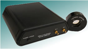
Features:
Two channels of voltage and temperature sensing & control (TSC)
USB powered (unless using TSC)
Waveforms generated internally
Independent SMB I/O Connectors for each channel
Multiple external control options
Includes USB and LabVIEW™ code example
Technical specifications:
| Fundamental Drive Waveform | 2 kHz AC square wave |
| Modulation Amplitude | 0-10 V rms (20 V rms available) |
| Modulation Resolution | 1 mV (0.155 mV using LabVIEW™ subroutines) |
| DC Offset | < 5 mV |
| Communications Interface | USB |
| LC Cell to Controller Connections | SMA-SMB, 2 m cable length |
| CE Compliance | Compliant |
| Modulation Waveforms | External modulation input (0-5 V) |
| Sinusoidal | |
| Triangle | |
| Square | |
| Sawtooth | |
| Transient nematic effect | |
| Temperature Control (2 channels) | Active heating/passive cooling to within ± 1˚C of nominal set point |
| Sync Output | TTL, user specified phase |
| Minimum System Requirements | |
| Windows™ Vista, 7 or 8 | |
| Requires LabVIEW™ version 2010 or higher for use with LabVIEW™ | |
| instrument library | |
| Item | Part Number |
| LC Digital Interface | STM-D5020 |
| LC Digital Interface (20V rms) | STM-D5020-20V |
| SMA to SMB Cables | STM-SMA-SMB |
| Sync Cables (SMB to BNC) | STM-SMB-BNC |
The Sintec Optronics TC3051 is a single channel, microprocessor based temperature controller specifically designed to work with Meadowlark Optics’ liquid crystal devices equipped with the Temperature Sensing and Control (TSC) option. The TC3051 requires minimal setup: connect the included power supply, connect the temperature control cable to both the TC3051 and the liquid crystal device and turn the power on.
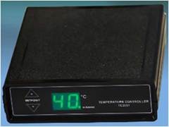
Features:
Stand alone
LED display
1 channel temperature control
Technical specifications:
| Power Requirements | 100 – 240V ac, 47 – 63 Hz, 500 mA |
| Fuse | Internal (not user serviceable) |
| Environment | 0° C to +50° C (Operating); -55°C to +100°C (Storage) |
| External Dimensions (W x D x H) | 5.08 x 5.25 x 1.50 in. (12.90 x 13.33 x 3.81 cm) |
| Weight | lb. (0.45 kg) |
| Temperature Readout Resolution | 1°C |
| Temperature Readout Range | 0°C to 99°C |
| Setpoint Resolution | 1°C |
| Setpoint Range | 20°C to 60°C |
| Temperature Controller | STM-TC3051 |
The FCS010 is a two‐channel liquid crystal controller specifically designed to drive our ferroelectric liquid crystal shutters and rotators. It has two short‐circuit protected output channels driven 180 degrees out of phase. The pre‐configured controller waveforms are optimized for FLC devices. We can tailor the waveform to your specific needs based on application and purchased FLC device. The drive waveform is output through SMA connectors. This controller is 100% RoHS compliant and is powered by a separate 12V international power supply.
Features:
Automatically DC balances
External modulation
10V output
Gate input
Drive I/O
Frequency range 1Hz - 10kHz
Technical specifications:
| Dimensions | 5.3 in. W x 5.3 in. L x 2.0 in. H , (13.5 cm W x 13.5 cm L x 5.1 cm H) |
| Number of LC Channels | Two, running identical programs 180 degrees out of phase |
| Output Waveform | Bipolar ± 15V peak voltage, ± 10V holding voltage |
| Amplitude Resolution | 16-bit; 1 mV voltage resolution |
| Internal Drive | 1 to 10,000 Hz, 50% duty cycle, frequency controlled by front-panel 10-turn knob |
| Ferroelectric Liquid Crystal Controller | STM-FCS010 |
A leading supplier and manufacturer of a wide range of photonics products such as lasers,laser parts & machines.
Office: 10 Bukit Batok Crescent #07-02 The Spire Singapore 658079
Tel: +65 63167112
Fax: +65 63167113
Whatsapp: +65 91904616