 English
 Français
 Deutsch
 euskara
 Русский язык
 Italiano
 Português
 Nederlands
 Polski
 Greek
Greek Lietuva
 Türkçe
 日本語
日本語 한어
한어 中文
中文 தாமில்
 فارسی
فارسی हिंदी
हिंदी Tiếng Việt
 ภาษาไทย
 Pilipino
 Indonesia
 தாமில்
Send us a message
CLOSE


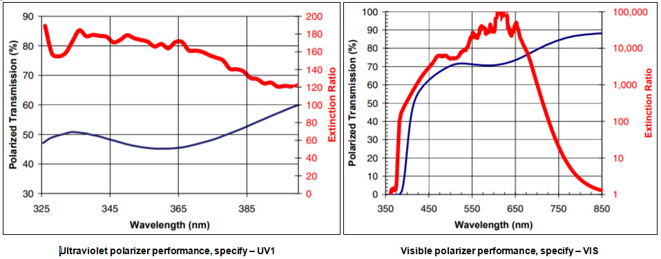
We manufacture Precision Linear Polarizers using dichroic sheet polarizer material laminated between high quality glass substrates. For visible wavelength polarizers, this construction produces a peak-to-valley transmitted wavefront distortion of less than λ/5. Various polarizer materials are used to cover wavelengths within 320 and 2000 nm. Both visible and near infrared polarizers are supplied with a high-efficiency, broadband antireflection (AR) coating; single-layer AR coatings are optional on our ultraviolet polarizers. Both mounted and unmounted Precision Linear Polarizers are offered as standard products. To facilitate use, our Precision Linear Polarizers have the transmission axis marked on the part.
| Substrate Material | |
| Ultraviolet | UV Grade Fused Silica |
| Visible | N-BK7 |
| Near Infrared | N-BK7 |
| Polarizer Material | Dichroic Polymer |
| Transmitted Wavefront Distortion (P-V @ 632.8 nm) | |
| Ultraviolet | ≤ λ/2 |
| Visible | ≤ λ/5 |
| Near Infrared | ≤ λ/2 |
| Surface Quality (scratch-dig) | 40-20 |
| Beam Deviation | |
| Ultraviolet | ≤ 2 arc-min |
| Visible | ≤ 1arc-min |
| Near Infrared | ≤ 2 arc-min |
| Reflectance (per surface, at normal incidence) | |
| Ultraviolet | ~4.25% (uncoated) |
| Visible | ≤ 0.5% |
| Near Infrared | ≤ 0.5% |
| Storage Temperature | |
| Ultraviolet | -50˚C to +50˚C |
| Visible | -50˚C to +50˚C |
| Near Infrared | -50˚C to +50˚C |
| Operating Temperature | |
| Ultraviolet | -50˚C to +50˚C |
| Visible | -50˚C to +50˚C |
| Near Infrared | -50˚C to +50˚C |
| Laser Damage Threshold | 1W/cm2, CW |
| 200 mJ/cm2, 20 ns, visible | |
| 2 J/cm2, 20 ns, 1064 nm | |
| Mounted | |||
| Diameter (in.) | Clear aperture (in.) | Thickness (in.) | Part number |
| 1.00 | 0.40 | 0.25 | STM-DPM-050-UV1 |
| 1.00 | 0.40 | 0.25 | STM-DPM-050-VIS |
| 1.00 | 0.40 | 0.25 | STM-DPM-050-NIR1 |
| 1.00 | 0.40 | 0.25 | STM-DPM-050-NIR2-n |
| 1.00 | 0.70 | 0.35 | STM-DPM-100-UV1 |
| 1.00 | 0.70 | 0.35 | STM-DPM-100-VIS |
| 1.00 | 0.70 | 0.35 | STM-DPM-100-NIR1 |
| 1.00 | 0.70 | 0.35 | STM-DPM-100-NIR2-n |
| 2.00 | 1.20 | 0.50 | STM-DPM-200-UV1 |
| 2.00 | 1.20 | 0.50 | STM-DPM-200-VIS |
| 2.00 | 1.20 | 0.50 | STM-DPM-200-NIR1 |
| 2.00 | 1.20 | 0.50 | STM-DPM-200-NIR2-n |
| Unmounted | |||
| 0.50 | 0.40 | 0.13 | STM-DP-050-UV1 |
| 0.50 | 0.40 | 0.13 | STM-DP-050-VIS |
| 0.50 | 0.40 | 0.14 | STM-DP-050-NIR1 |
| 0.50 | 0.40 | 0.14 | STM-DP-050-NIR2-n |
| 1.00 | 0.80 | 0.26 | STM-DP-100-UV1 |
| 1.00 | 0.80 | 0.26 | STM-DP-100-VIS |
| 1.00 | 0.80 | 0.27 | STM-DP-100-NIR1 |
| 1.00 | 0.80 | 0.27 | STM-DP-100-NIR2-n |
* Custom AR coatings are available on all polarizers. For NIR2 polarizers, please choose from the following AR coating options: NIR2 – 1 covers 650 – 950 nm; NIR2 – 2 covers 900 – 1250 nm; NIR2 – 3 covers 1200 – 1700 nm
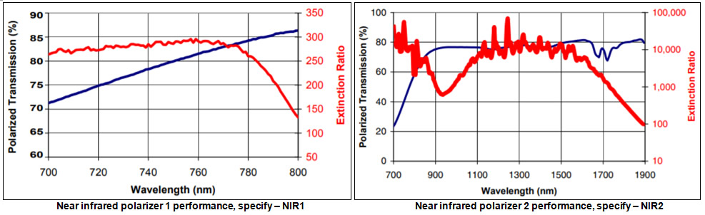
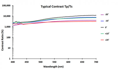
In response to the need for improved contrast in the near infrared region, Sintec Optronics now offers a line of High Contrast Linear Polarizers. These polarizers are constructed by laminating Polarcor™ dichroic glass polarizers between high quality glass substrates to achieve superior wavefront performance and surface quality. Sintec Optronics High Contrast Linear Polarizers offer the performance of calcite polarizers in large apertures. Contrast ratios are available as high as 10,000:1. Custom wavelength ranges from 630 to 1580 nm with 60 to 80 nm bandpasses and sizes from 10 to 25 mm are available.
Features:
Typical transmission for a High Contrast Linear Polarizer centered at 800 nm. Extinction ratio is measured a Glan-Thompson polarizer
| Substrate Material | N-BK7 |
| Polarizer Material | Dichroic Glass |
| Transmitted Wavefront Distortion | ≤ λ/4 |
| (P-V @ 632.8 nm) | |
| Surface Quality (scratch-dig) | 40-20 |
| Beam Deviation | ≤ 3 arc-min |
| Reflectance (per surface, | ≤ 0.5% |
| at normal incidence) | |
| Storage Temperature | -50˚C to +70˚C |
| Operating Temperature | -50˚C to +70˚C |
| Laser Damage Threshold | 1W/cm2, CW 200 |
| mJ/cm2, 20 ns, visible | |
| 2 J/cm2, 20 ns, 1064 nm |
| Clear aperture in. [mm] | Thickness ±0.020 in. [±0.51 mm] | Diameter ± 0.005 in. [±0.13 mm] | Part Number |
| 0.4 | 0.25 | Ø1.00 | STM-PPM-050-λ |
| [10.2] | [6.35] | [Ø25.4] | |
| 0.7 | 0.35 | Ø1.00 | STM-PPM-100-λ |
| [17.8] | [8.89] | [Ø25.4] |
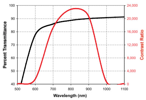
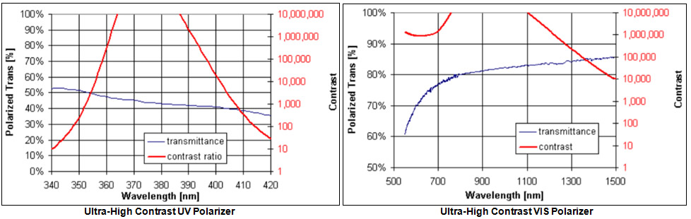
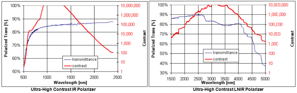
Our UHPUV series polarizers offer high contrast in the UV from 360 to 400 nm and our UHP-LNIR series polarizers offer high contrast over the exceptionally broad range from 650 to 5000 nm.
| Substrate Material | |
| Ultraviolet | UV Grade Fused Silica |
| Visible | N-BK7 |
| Infrared | N-BK7 |
| WIR/MWIR | Design dependent |
| Polarizer Material | Dichroic Glass |
| Transmitted Wavefront Distortion (P-V @ 632.8 nm) | |
| Ultraviolet | ≤ 1λ per Ø10mm |
| Visible | ≤ 1λ per Ø10mm |
| Infrared | ≤ 1λ per Ø10mm |
| SWIR/MWIR | Design Dependent |
| Surface Quality (scratch-dig) | 40-20 |
| Beam Deviation | |
| Ultraviolet | ≤ 5arc-min |
| Visible | ≤ 5arc-min |
| Infrared | ≤ 5arc-min |
| SWIR/MWIR | ≤ 10 arc-min/12.5 mm |
| ≤ 5 arc-min/25mm | |
| Reflectance (per surface, at normal incidence) | ~4.25% |
| Storage Temperature | |
| Ultraviolet | -20˚C to +50˚C |
| Visible | -20˚C to +50˚C |
| Infrared | -20˚C to +50˚C |
| SWIR/MWIR | -50˚C to +400˚C |
| Operating Temperature | |
| Ultraviolet | -20˚C to +50˚C |
| Visible | -20˚C to +50˚C |
| Infrared | -20˚C to +50˚C |
| SWIR/MWIR | -50˚C to +400˚ C |
| Mounted and Laminated | |||
| Clear aperture in. [mm] | Thickness in. [mm] | Diameter ± 0.005 in. [± 0.13 mm | Part Number |
| 0.4 | 0.25 | Ø1.00 | STM-UPM-050-UV |
| [10.2] | [6.35] | [Ø25.4] | |
| 0.4 | 0.25 | Ø1.00 | STM-UPM-050-VIS |
| [10.2] | [6.35] | [Ø25.4] | |
| 0.4 | 0.25 | Ø1.00 | STM-UPM-050-IR |
| [10.2] | [6.35] | [Ø25.4] | |
| 0.7 | 0.35 | Ø1.00 | STM-UPM-100-UV |
| [17.8] | [8.89] | [Ø25.4] | |
| 0.7 | 0.35 | Ø1.00 | STM-UPM-100-VIS |
| [17.8] | [8.89] | [Ø25.4] | |
| 0.7 | 0.35 | Ø1.00 | STM-UPM-100-IR |
| [17.8] | [8.89] | [Ø25.4] | |
| Mounted and Unlaminated | |||
| 0.4 | 0.185 | Ø1.00 | STM-UPM-050-MIR |
| [10.2] | [4.70] | [Ø25.4] | |
| 0.7 | 0.185 | Ø1.00 | STM-UPM-100-MIR |
| [17.8] | [4.70] | [Ø25.4] | |
| Unmounted and Laminated | |||
| Clear aperture in. [mm] | Thickness in. [mm] | Diameter ± 0.010 in. [±0.25 mm] | Part Number |
| 0.4 | 0.14 | Ø0.50 | STM-UHP-050-UV |
| [10.2] | [3.56] | [Ø12.7] | |
| 0.4 | 0.14 | Ø0.50 | STM-UHP-050-VIS |
| [10.2] | [3.56] | [Ø12.7] | |
| 0.4 | 0.14 | Ø0.50 | STM-UHP-050-IR |
| [10.2] | [3.56] | [Ø12.7] | |
| 0.8 | 0.26 | Ø1.00 | STM-UHP-100-UV |
| [20.3] | [6.60] | [Ø25.4] | |
| 0.8 | 0.26 | Ø1.00 | STM-UHP-100-VIS |
| [20.3] | [6.60] | [Ø25.4] | |
| 0.8 | 0.26 | Ø1.00 | STM-UHP-100-IR |
| [20.3] | [6.60] | [Ø25.4] | |
| Unmounted and Unlaminated | |||
| 0.4 | 0.008 | Ø0.50 | STM-UHP-050-MIR |
| [10.2] | [0.203] | [Ø12.7] | |
| 0.8 | 0.008 | Ø1.00 | STM-UHP-100-MIR |
| [20.3] | [0.203] | [Ø25.4] | |
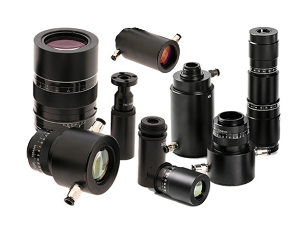
By precisely controlling internal prism angles in these calcite polarizers, a very efficient linear polarizer is produced. Sintec Optronics offers Glan-Thompson Polarizers, intended for precision optical instrumentation and low power laser applications. Key advantages of Glan-Thompson Polarizers include excellent extinction ratio performance and a broad sp ectral range. Our Glan-Thompson Polarizers are supplied in a black anodized cylindrical housing for easy mounting.
| Wavelength Range | 320 - 2300 nm |
| Substrate Material | Grade A Optical Calcite |
| Beam Deviation | ± 3 arc-min |
| Reflectance (per surface, at normal incidence) | |
| Uncoated | ~4.5% |
| Single Layer MgF2 | ~1.5% |
| Contrast Ratio | 10,000:1 over central |
| 2/3 of clear aperture | |
| Acceptance Angle | ± 5˚ |
| Laser Damage Threshold | 25-30 W/cm2 CW |
| Clear aperture (mm) | Wavelength range (mm) | AR coating | Part Number |
| .197 [5.0] | 320-2300 | none | STM-GTP-M05 |
| .197 [5.0] | 400-700 | MgF2 | STM-GTP-M05-0550 |
| .197 [5.0] | 650-1000 | MgF2 | STM-GTP-M05-0825 |
| .197 [5.0] | 1000-1500 | MgF2 | STM-GTP-M05-1250 |
| .31 [7.9] | 320-2300 | none | STM-GTP-M08 |
| .31 [7.9] | 400-700 | MgF2 | STM-GTP-M08-0550 |
| .31 [7.9] | 650-1000 | MgF2 | STM-GTP-M08-0825 |
| .31 [7.9] | 1000-1500 | MgF2 | STM-GTP-M08-1250 |
| .39 [9.9] | 320-2300 | none | STM-GTP-M08 |
| .39 [9.9] | 400-700 | MgF2 | STM-GTP-M10-0550 |
| .39 [9.9] | 650-1000 | MgF2 | STM-GTP-M10-0825 |
| .39 [9.9] | 1000-1500 | MgF2 | STM-GTP-M10-1250 |
Sintec Optronics provides an extremely broadband polarizer solution. Manufactured for a wavelength range of 300 to 2700 nm rivaling the span of a Glan-Thompson calcite polarizer, this optic is ideal for broadband applications. The proprietary composition of the Ultra Broadband Polarizer allows for an unprecedented width of spectral range at a fraction of the cost of other competing polarizers. This cost savings is coupled with a thickness of only 0.182” including mount and solid contrast ratio through the entire range from UV to IR.
| Stock Options | |
| Substrate Material | UV Grade Fused Silica |
| Wavelength Range | 300-2700 nm, uncoated |
| Transmitted Wavefront Distortion | ± 3.5 λ per inch (P-V@ 633 nm) |
| *Custom options available for | [≤ 1 λ per inch (RMS @ 633 nm)] |
| Improvement of TWD | |
| Surface Quality | 80-50 scratch-dig |
| Acceptance Angle | ± 40˚ |
| Laser Damage Threshold | 0.80 J/cm2 at 355 nm |
| 0.20 J/cm2 at 532 nm | |
| 0.30 J/cm2 at 1064 nm | |
| Operating Temperature | -50˚C to + 50˚C |
| Substrate Thickness | Polarizer Thickness ~ 0.087 in. |
| Mount Thickness 0.182 in. | |
| Custom Options | |
| Size | 0.5”- 4.0” |
| Shape | Customer specified |
| Clear Aperture in. (mm) | Dimensions in. (mm) | Part number |
| Ø0.75 | Ø1.00 | STM-GPM-100-UNC |
| [19.3 mm] | [Ø25.4 mm] | |
| Ø1.25 | Ø1.50 | STM-GPM-150-UNC |
| [32.0 mm] | [Ø38.1 mm] | |
| Ø1.75 | Ø2.00 | STM-GPM-200-UNC |
| [44.7 mm] | [Ø50.8 mm] |
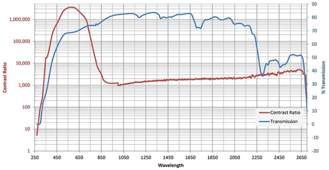
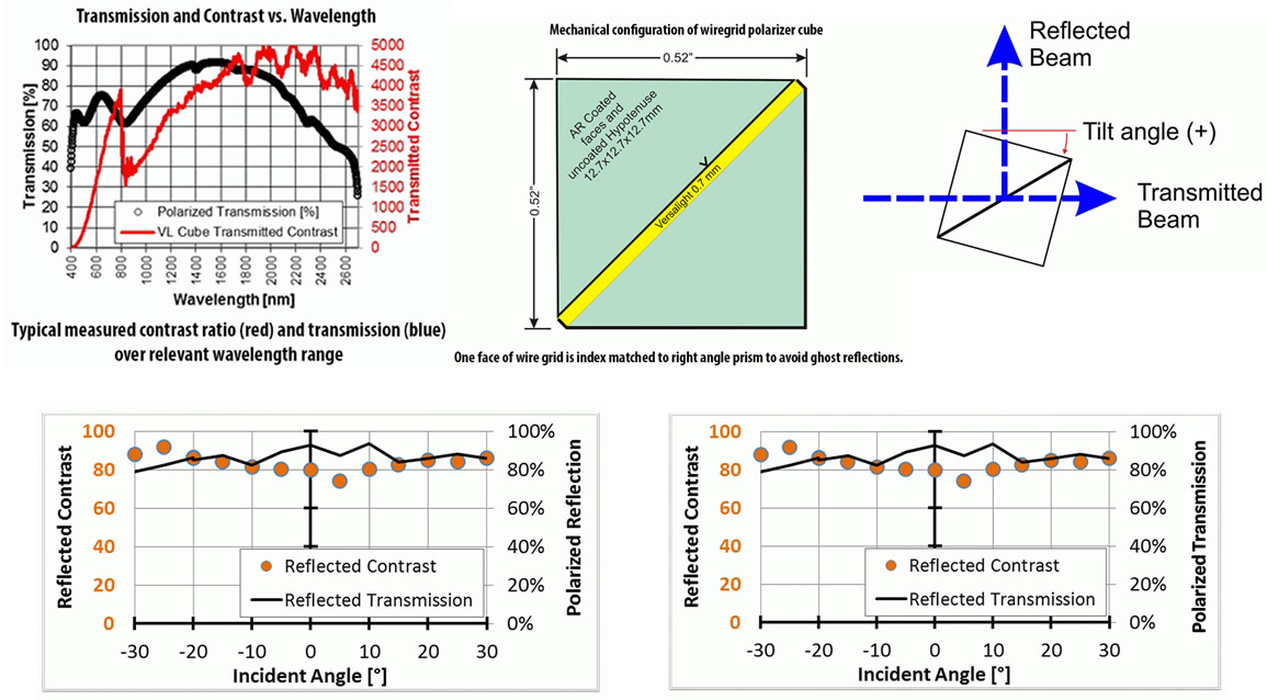
Typical measured contrast and transmission over relevant wavelength range
This polarizer is a wire grid on an antireflection coated silicon substrate optimized for 3 to 6 microns. The ring mounting provides for ease of handling and has the polarization transmission direction marked. The wire grid surface is quite delicate and should only be cleaned non-mechanically. Standard outer diameters are one and two inch but custom sizes, shapes and unmounted polarizers are also available.
| Substrate Material | Silicon, 0.7 mm thickness |
| AR Coating | Doubled sided AR |
| Wavelength Range | 3 µm to 6 µm |
| Contrast Ratio | See graph |
| Acceptance Angle | ≤ 20˚ |
| Transmitted Wavefront Distortion | ≤ 1.5 λ (P - V at 4 mm) |
| (per inch) | [≤ λ/3 (RMS at 4 mm)] |
| Beam Deviation | ≤ 2 arc min |
| Maximum Aperture | Up to 4 in. circular |
| Surface Quality | 80-50 scratch-dig |
| Clear aperture in. [mm] | Thickness in. [mm] | Diameter in. [mm] | Part Number |
| Ø0.76 | 0.182 | Ø1.00 | STM-MPM-100 |
| [19.3] | [4.62] | [Ø25.4] | |
| Ø1.76 | 0.182 | Ø2.00 | STM-MPM-200 |
| [44.7] | [4.62] | [Ø50.8] |
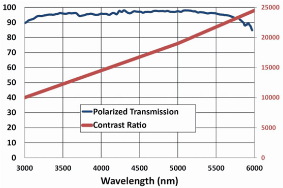
Typical measured contrast and transmission over relevant wavelength range
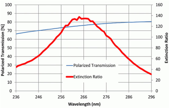
Developed for wavelengths between 245 and 285 nm, this polarizer is ideal for applications around 266 nm. Additionally, this polarizer is transparent in the visible range, allowing visible light to easily pass through. The UV Polarizer has a proprietary structure that allows for a high laser damage threshold. Custom shapes and sizes are possible due to the large manufactured substrates.
| Substrate Material | Fused Silica, 1.0 mm thick |
| Wavelength Range | 245 - 285 nm |
| Transmitted Wavefront Distortion | ≤ λ/2 (P - V @ 633 nm) |
| [≤ λ/8 (RMS @ 633 nm)] | |
| Surface Quality | 40-20 scratch-dig |
| Beam Deviation | ≤ 5 arc-min |
| Acceptance Angle | 0˚± 6˚ |
| Clear aperture in. [mm] | Dimensions in. [mm] | Part number |
| Mounted Square | ||
| Up to 1.20 [30.5] | Up to 2.00 [50.8] | Custom options available – please inquire |
| Unmounted Square | ||
| 0.4 | 0.5 | STM-DUV-050-0266S |
| [10.2] | [2.7] | |
| 0.8 | 1 | STM-DUV-100-0266S |
| [20.3] | [25.4] | |
Typical measured contrast and transmission over relevant wavelength range
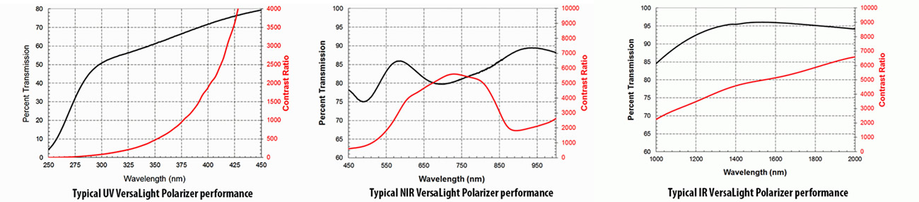
VersaLight™ is constructed of a thin layer of aluminum MicroWires® on a glass substrate and sets a new standard for applications requiring high durability, contrast and a wide field of view for visible through infrared wavelengths. VersaLight™ offers the performance quality of dichroic sheet polarizers while extending the operating temperature to 200° C. The nature of VersaLight’s MicroWire construction allows it to perform as an exceptional polarizing beam splitter. In operation, VersaLight™ reflects one polarization state and transmits another, both with high contrast. VersaLight™ offers the broadest band and highest field of view of any polarizer material presently available. VersaLight™ can be shaped as needed and stacked to achieve very high contrast ratios. Large aperture VersaLight™ Polarizers are available on a custom basis, up to 200m rounds.

| Wavelength Range | |
| Ultraviolet | 325 nm to 450 nm |
| Near infrared | 450 nm to 1000 nm |
| Infrared | 1000 nm to 2000 nm |
| Substrate Material | |
| Ultraviolet | UV Grade Fused Silica |
| Near nfrared | Eagle XG® |
| Infrared | Eagle XG® |
| Transmitted Wavefront Distortion (P-V @ 632.8 nm) | |
| Ultraviolet | ~ λ/4 per in. |
| Near Infrared | ~ 5λ per in. |
| Infrared | ~ 5λ per in. |
| Surface Quality (scratch-dig) | 80-50 |
| Beam Deviation | ≤ 1arc-min |
| Contrast Ratio (see graph) | Typ. Reflection > 80:1 |
| Typ. Transmission > 2000:1 | |
| Maximum Temperature | 200° C for single layer |
| Laser Damage Threshold | 10 KW/cm2, CW, 1540 nm |
* On ultraviolet Versalight, the wire grid surface will be unprotected, fragile and cannot be touched. UV VersaLight is optimized for 300-450 nm; NIR VersaLight is optimized for 450-1000 nm; IR VersaLight is optimized for 1000-2000 nm.
| Square | ||
| Thickness ± .002 in. [± 0.05 mm] | Diameter +0/-0.010 in. [+0/-0.25 mm] | Part number |
| 0.039 | 0.5 × 0.5 | STM-VLS-050-UV |
| [1.0] | [12.7 × 12.7] | |
| 0.028 | 0.5 × 0.5 | STM-VLS-050-NIR |
| [0.7] | [12.7 × 12.7] | |
| 0.028 | 0.5 × 0.5 | STM-VLS-050-IR |
| [0.7] | [12.7 × 12.7] | |
| 0.039 | 1.0 × 1.0 | STM-VLS-100-UV |
| [1.0] | [25.4 × 25.4] | |
| 0.028 | 1.0 × 1.0 | STM-VLS-100-NIR |
| [0.7] | [25.4 × 25.4] | |
| 0.028 | 1.0 × 1.0 | STM-VLS-100-IR |
| [0.7] | [25.4 × 25.4] | |
| 0.039 | 2.0 × 2.0 | STM-VLS-200-UV |
| [1.0] | [50.8 × 50.8] | |
| 0.028 | 2.0 × 2.0 | STM-VLS-200-NIR |
| [0.7] | [50.8 × 50.8] | |
| 0.028 | 2.0 × 2.0 | STM-VLS-200-IR |
| [0.7] | [50.8 × 50.8] | |
| Round | ||
| 0.039 | Ø0.5 | STM-VLR-050-UV |
| [1.0] | [Ø12.7] | |
| 0.028 | Ø0.5 | STM-VLR-050-NIR |
| [0.7] | [Ø12.7] | |
| 0.028 | Ø0.5 | STM-VLR-050-IR |
| [0.7] | [Ø12.7] | |
| 0.039 | Ø1.0 | STM-VLR-100-UV |
| [1.0] | [Ø25.4] | |
| 0.028 | Ø1.0 | STM-VLR-100-NIR |
| [0.7] | [Ø25.4] | |
| 0.028 | Ø1.0 | STM-VLR-100-IR |
| [0.7] | [Ø25.4] | |
| 0.039 | Ø2.0 | STM-VLR-200-UV |
| [1.0] | [Ø50.8] | |
| 0.028 | Ø2.0 | STM-VLR-200-NIR |
| [0.7] | [Ø50.8] | |
| 0.028 | Ø2.0 | STM-VLR-200-IR |
| [0.7] | [Ø50.8] | |
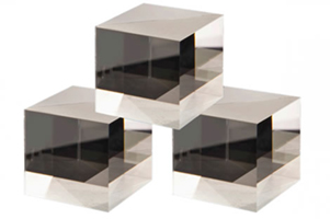
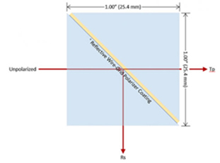
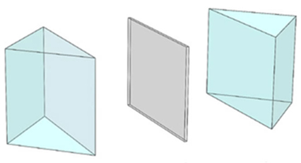
Sintec Optronics presents its Versalight wire grid polarizing beam splitters. Manufactured for wavelength ranges between 420 and 2600 nm, this polarizer is ideal for broadband and wide field-of-view applications. Wire grid polarizing beam splitters are manufactured out of our Versalight wire grid polarizer sandwiched between right angle prisms. No AR coatings are standard for maximum wavelength usage. Broadband AR coatings are available on the faces of the cube covering either visible (450 to 1100 nm) or IR (1000 to 2400 nm.)
| Substrate Material | N-BK7 (or equivalent) |
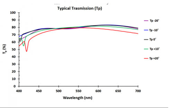
| Average Reflectivity | 450-1100 nm - VIS - < 2.0 % |
| Infrared1000-2400 nm - IR - < 2.0 % | |
| 420-2600 nm - UNC - ~4.25% | |
| Transmitted Wavefront Distortion | ≤ λ/2 (P-V @ 633 nm) |
| [≤ λ/8 (RMS @ 633 nm)] | |
| Surface Quality | 80-50 scratch-dig |
| Beam Deviation (transmittance) | ≤ 5 arc-min |
| Dimensional Tolerance | ± 0.020 in. |
| Acceptance Angle | ± 40˚ |
| Operating Temperature | -40˚C to +75˚C |
| Unmounted | ||
| Clear aperture in. [mm] | Dimensions in. [mm] | Part number |
| 0.40 in. [10.2] | 0.52 × 0.52 × 0.50 [13.2 × 13.2 × 12.7] | STM-BV-050-VIS |
| STM-BV-050-IR | ||
| STM-BV-050-UNC | ||
| 0.80 in. [20.3] | 1.02 × 1.02 × 1.00 [25.9 × 25.9 × 25.4] | STM-BV-100-VIS |
| STM-BV-100-IR | ||
| STM-BV-100-UNC | ||
| 1.60 in. [40.6] | 2.02 × 2.02 × 2.00 [51.3 × 51.3 × 50.8] | STM-BV-200-VIS |
| STM-BV-200-IR | ||
| STM-BV-200-UNC | ||
KEY FEATURES
This polarizing beam splitter (PBS) cube is optimized for use over a wide range of acceptance angles while maintaining color uniformity and image contrast in the visible wavelength ranges. The ICE Cube allows compact optical designs with reduced optical paths. Engineers are now able to design smaller systems while maintaining excellent optical performance. The ICE Cube polarizer performance exceeds that for the commonly used thin film MacNeille cubes in both acceptable wavelength range and angle of incidence range while providing more than twice the contrast ratio in the transmitted beam for most wavelengths.
The ICE Cube is assembled by embedding our polarizing beam splitter plate between two AR coated glass prisms. These cubes are designed with Nanowire® grid structures centered on the hypotenuse of the ICE Cube. The ICE Cube PBS separates natural light into two main orthogonal, linearly polarized components; the p-polarized light which is transmitted while the s-polarized light is reflected at a 90 degree angle. In principle, half of the incident light is reflected, and the other half is transmitted.
| Substrate material | N-BK7 |
| Operating wavelength | 400-700nm (typical average for azimuthal) |
| Average reflectivity | <0.5%@400-700 (4x cube faces) |
| Transmitted wavefront distortion | £λ/3 (typical @633nm) |
| Surface quality | 40-20 scratch-dig |
| Beam deviation | £5arc min |
| Dimensional tolerance | +0.0mm/-0.25mm |
| Acceptance angle | Up to ±25o |
| Maximum temperature | 90oC |
Many options, including custom wavelengths and sizes are available.
Part number: STBV-100-ICE (unmounted, dimension 1x1x1in, clear aperture 0.90in)
Right-angle prisms are matched in pairs to produce high quality laser line beamsplitting polarizers with superior wavefront quality in both transmission and reflection. The hypotenuse face of one prism is coated with a multilayer dielectric beamsplitting coating optimized for laser performance. Two prisms are cemented together, protecting the critical coating from performance-degrading environmental factors. Each cube separates an unpolarized incident beam into two orthogonal, linearly polarized components with negligible absorption. Following the principle of pile-of-plates polarizers, p-polarized light is transmitted with approximatley 1000:1 contrast and s-polarization is reflected with approximatley 20:1 contrast. These polarizers perform best with collimated or near-collimated light.
| Substrate | N-BK7 |
| Transmitted Wavefront Distortion | ≤ λ/5 for p-polarized beam |
| (P-V @ 632.8 nm) | |
| (P-V @ 632.8 nm) | |
| Surface Quality (scratch-dig) | 40-20 |
| Beam Deviation | |
| Transmitted | ≤ 3 arc-min |
| Reflected | ≤ 6 arc-min |
| Reflectance (per surface) | ≤ 0.5% |
| Contrast Ratio | |
| Transmitted | ≤ 500:1 |
| Reflected | ≤ 20:1 |
| Transmission | |
| p-polarized light | ≥ 95% transmitted |
| s-polarized light | ≥ 99% reflected |
| Acceptance Angle | ± 2˚ |
| Storage Temperature | -40˚C to +100˚C |
| Operating Temperature | -40˚C to +100˚C |
| Laser Damage Threshold | 500 W/cm2, CW |
| 300 mJ/cm2, 10 ns, visible | |
| 200 mJ/cm2, 10 ns, 1064 nm | |
| Dimensions ± 0.020 in. [± 0.51 mm] | Part number |
| 0.50 × 0.50 x 0.50 | STM-BP-050-λ |
| [12.7 x 12.7 x 12.7] | |
| 1.00 × 1.00 × 1.00 | STM-BP-100-λ |
| [25.4 × 25.4 × 25.4] |
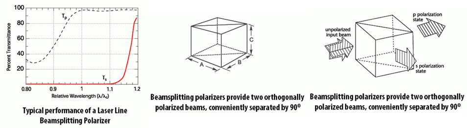
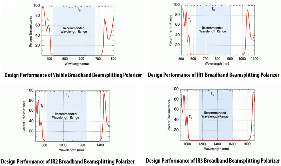
For applications involving broadband or tunable wavelength sources, Sintec Optronics presents a line of Broadband Beamsplitting Polarizers covering the visible to near infrared region. These cubes offer increased utility for a range of polarization needs. As with the Laser Line Beamsplitting Polarizers, two usable polarization forms result, conveniently separated by 90°. For unpolarized input, incident light will be equally split, 50% transmitted and reflected. Varying the input polarization axis will change the split ratio. These broadband designs require well-collimated input and accurate angular alignment for optimal performance. All four entrance and exit faces are antireflection coated to minimize losses.
| Wavelength Range | |
| Visible | 440-680 nm |
| Near IR1 | 620-900 nm |
| Near IR2 | 820-1250 nm |
| Near IR3 | 1150-1600 nm |
| Substrate Material | SF 2 |
| Transmitted Wavefront Distortion | ≤ λ/5 for p-polarized beam |
| (P-V @ 632.8 nm) | |
| (P-V @ 632.8 nm) | |
| Beam Deviation | |
| Transmitted | ≤ 3 arc-min |
| Reflected | ≤ 6 arc-min |
| Reflectance (per surface) | ≤ 0.5% |
| Contrast Ratio | |
| Transmitted | ≥ 500:1 |
| Reflected | ≥ 20:1 |
| Transmission | |
| p-polarized light | ≥ 95% transmitted |
| s-polarized light | ≥ 98% reflected |
| Clear Aperture | Central 80% diameter |
| Acceptance Angle | ± 2˚ |
| Storage Temperature | -40˚C to +100˚C |
| Operating Temperature | -40˚C to +100˚C |
| Laser Damage Threshold | 500 W/cm2, CW |
| 300 mJ/cm2, 10 ns, visible | |
| 200 mJ/cm2, 10 ns, 1064 nm | |
| Clear aperture | Dimensions ± 0.020 in. [± 0.51 mm] | Part number |
| Visible (440-680) | ||
| 0.40 × 0.40 × 0.40 | 0.50 × 0.50 × 0.50 | STM-BB-050-VIS |
| [10.2 x 10.2 x 10.2] | [12.7 x 12.7 x 12.7] | |
| 0.80 × 0.80 × 0.80 | 1.00 × 1.00 × 1.00 | STM-BB-100-VIS |
| [20.3 × 20.3 × 20.3] | [25.4 × 25.4 × 25.4] | |
| Near IR1 (620-900 nm) | ||
| 0.40 × 0.40 × 0.40 | 0.50 × 0.50 × 0.50 | STM-BB-050-IR1 |
| [10.2 x 10.2 x 10.2] | [12.7 x 12.7 x 12.7] | |
| 0.80 × 0.80 × 0.80 | 1.00 × 1.00 × 1.00 | STM-BB-100-IR1 |
| [20.3 × 20.3 × 20.3] | [25.4 × 25.4 × 25.4] | |
| Near IR2 (820-1250 nm) | ||
| 0.40 × 0.40 × 0.40 | 0.50 × 0.50 × 0.50 | STM-BB-050-IR2 |
| [10.2 x 10.2 x 10.2] | [12.7 x 12.7 x 12.7] | |
| 0.80 × 0.80 × 0.80 | 1.00 × 1.00 × 1.00 | STM-BB-100-IR2 |
| [20.3 × 20.3 × 20.3] | [25.4 × 25.4 × 25.4] | |
| Near IR3 (1150-1600 nm) | ||
| 0.40 × 0.40 × 0.40 | 0.50 × 0.50 × 0.50 | STM-BB-050-IR3 |
| [10.2 x 10.2 x 10.2] | [12.7 x 12.7 x 12.7] | |
| 0.80 × 0.80 × 0.80 | 1.00 × 1.00 × 1.00 | STM-BB-100-IR3 |
| [20.3 × 20.3 × 20.3] | [25.4 × 25.4 × 25.4] | |
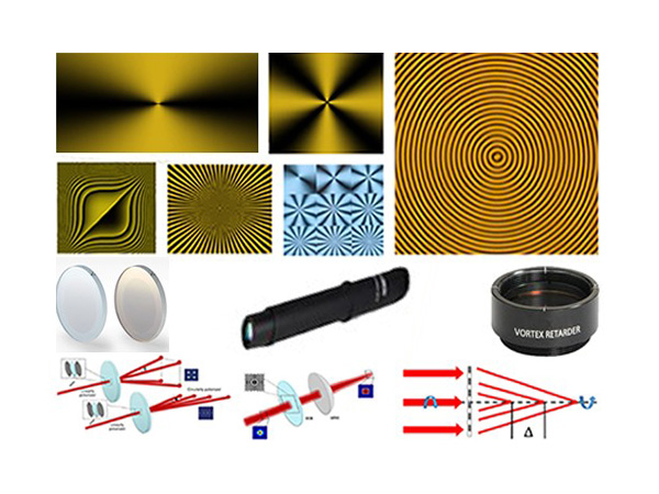
Dichroic Circular Polarizers consist of a dichroic linear polarizer and true zero-order quarterwave retarder. Precisely aligning the retarder fast axis at 45° to the linear polarization direction ensures optimum performance. True zero-order retarders are used in the assembly of our Dichroic Circular Polarizers and tight retardance tolerances contribute to the final performance.
| Standard Wavelengths | 532, 632.8, 670, 780, 850, 1064, and 1550 nm |
| Substrate Material | N-BK7 |
| Polarizer Material | Dichroic Polymer |
| Retarder Material | Birefringent Polymer |
| Transmitted Wavefront Distortion (P-V @ 632.8 nm) | |
| Visible | ≤ λ/5 |
| Near Infrared | ≤ λ/2 |
| Beam Deviation | |
| Visible | ≤ 1 arc-min |
| Near Infrared | ≤ 2 arc-min |
| Surface Quality (scratch-dig) | 40-20 |
| Reflectance (per surface) | ≤ 0.5% |
| Isolation | >99.8% |
| Storage Temperature | -20˚C to +50˚C |
| Operating Temperature | -20˚C to +50˚C |
| Laser Damage Threshold | 1 W/cm2, CW |
| Mounted | |||
| Clear aperture in. [mm] | Thickness in. [mm] | Diameter ± 0.005 in. [± 0.13 mm] | Part number |
| 0.4 | 0.25 | Ø1.00 | STM-CPM-050-λ |
| [10.2] | [6.35] | [Ø25.4] | |
| 0.7 | 0.35 | Ø1.00 | STM-CPM-100-λ |
| [17.8] | [8.9] | [Ø25.4] | |
| 1.2 | 0.5 | Ø2.00 | STM-CPM-200-λ |
| [30.5] | [12.7] | [Ø50.8] | |
| Unmounted | |||
| Clear aperture in. [mm] | Thickness in. [mm] | Diameter +0/-0.010 in. [+0/-0.25 mm] | Part Number |
| 0.4 | 0.13 | Ø0.50 | STM-CP-050-λ |
| [10.2] | [3.3] | [Ø12.7] | |
| 0.8 | 0.26 | Ø1.00 | STM-CP-100-λ |
| [20.3] | [6.6] | [Ø25.4] | |
High Contrast Thin Film Polarizers (TFP) are made using advanced Ion Beam Sputtering (IBS) coating technology. These thin film polarizers separate s- and p-polarization components of high energy laser beams. Due to very low losses they are perfect for intra and extra cavity usage. Because of their high damage threshold and extinction ratio (>1000:1), thin film polarizers are a good replacement for Glan laser polarizing prisms or polarizing cube beam splitters. For optimal performance, polarizers should be mounted in an appropriate holder allowing angular adjustment. We offer two types of high contrast polarizers: with higher LIDT or higher contrast values.
| Wave-length, nm | Transmission, p-pol, % | Reflection, s-pol, % | Contrast, (Tp/Ts) | Typical LIDT @ 10 ns, 10 Hz for s-pol, J/cm2 | Typical LIDT @ 10 ns, 10 Hz for p-pol, J/cm2 | Product ID for AOI=Brewster |
| 343 | >97 | >99.7 | >300:1 | >4 | >1 | 2-HCBTFP-0343-0254 |
| 355 | >97 | >99.7 | >300:1 | >4 | >1 | 2-HCBTFP-0355-0254 |
| 515 | >99 | >99.9 | >1000:1 | >5 | >2 | 2-HCBTFP-0515-0254 |
| 532 | >98 | >99.8 | >500:1 | >7 | >3 | 2-HCPBTFP-0532-0254 |
| 532 | >99 | >99.9 | >1000:1 | >5 | >2 | 2-HCBTFP-0532-0254 |
| 800 | >99 | >99.9 | >1000:1 | >7 | >3 | 2-HCBTFP-0800-0254 |
| 1030 | >99 | >99.8 | >500:1 | >20 | >10 | 2-HCPBTFP-1030-1020 |
| 1030 | >99 | >99.9 | >1000:1 | >7 | >3 | 2-HCBTFP-1030-0254 |
| 1064 | >99 | >99.8 | >500:1 | >20 | >10 | 2-HCPBTFP-1064-1020 |
| 1064 | >99 | >99.9 | >1000:1 | >7 | >3 | 2-HCBTFP-1064-0254 |
| Wave-length, nm | Transmission, p-pol, % | Reflection, s-pol, % | Contrast, (Tp/Ts) | Typical LIDT @ 10 ns, 10 Hz for s-pol, J/cm2 | Typical LIDT @ 10 ns, 10 Hz for p-pol, J/cm2 | Product ID for AOI=45o |
| 355 | >95 | >99.8 | >500:1 | >4 | >1 | 2-HC45TFP-0355-0254 |
| 532 | >98 | >99.8 | >500:1 | >7 | >3 | 2-HCP45TFP-0532-0254 |
| 532 | >97 | >99.9 | >1000:1 | >5 | >2 | 2-HC45TFP-0532-0254 |
| 1030 | >97 | >99.8 | >500:1 | >20 | >10 | 2-HCP45TFP-1030-0254 |
| 1030 | >97 | >99.8 | >1000:1 | >7 | >3 | 2-HC45TFP-1030-0254 |
| 1064 | >97 | >99.8 | >500:1 | >20 | >10 | 2-HCP45TFP-1064-0254 |
| 1064 | >97 | >99.9 | >1000:1 | >7 | >3 | 2-HC45TFP-1064-0254 |
* Customized solutions are available on request. Typical dimensions are Ø25.4 x 5 mm, 20 x 40 x 5 mm and 10 x 20 x 5 mm.
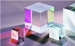
Polarizing beamsplitter cubes offer several advantages over plate beamsplitters. They are easy to handle, high contrast and high extinction ratio polarizers that split a randomly polarized beam into two orthogonal linearly polarized components. These products are typically used in laser beam separation, combination and optical-isolation applications. The epoxy-free construction of the cubes enables a superior performance at high energy levels.
| Wavelength, nm | Dimensions, mm | Reflection s-pol, % |
Transmission p-pol, % | Product ID |
| 345-365 (centered @ 355) | 12.7x12.7x12.7 | >99.5 | >96 | 2-HPCB-A-0125 |
| 25.4x25.4x25.4 | >99.5 | >96 | 2-HPCB-A-0254 | |
| 510-550 (centered @ 532) | 12.7x12.7x12.7 | >99.5 | >97 | 2-HPCB-B-0125 |
| 25.4x25.4x25.4 | >99.5 | >97 | 2-HPCB-B-0254 | |
| 1020-1090 (centered @ 1064) | 12.7x12.7x12.7 | >99.5 | >97 | 2-HPCB-C-0125 |
| 25.4x25.4x25.4 | >99.5 | >97 | 2-HPCB-C-0254 | |
| 1510-1580 (centered @ 1550) | 12.7x12.7x12.7 | >99.5 | >97 | 2-HPCB-D-0125 |
| Type | Material | Characters |
| Glan-Taylor | Calcite(350~2300nm) α-BBO(190~3500nm) YVO4 (500~4000nm) |
Air spaced, nearly Brewster cut, not suitable for high power laser |
| Glan-laser | Calcite(350~2300nm) α-BBO (190~3500nm) YVO4 (500~4000nm) |
Air spaced, nearly Brewster cut, with windows, suitable for high power laser |
| Glan-Thompson | Calcite(350~2300nm) α-BBO(190~3500nm) |
Glue contacted, wide accept angle, not suitable for high power laser |
| Brewster Polarizers | Calcite(350~2300nm) YVO4 (500~4000nm) |
High transmission:Tp>98% High damage threshold |
| Glan-Thompson PBS | Calcite(350~2300nm) α-BBO(190~3500nm) |
used to separate o and e light 45 degree |
| Wollaston | Calcite(350~2300nm) Crystal Quartz (200~300nm) YVO4 (500~4000nm) |
Glue contacted or Optical contacted, separate o and e light |
| Rochon Polarizers | Crystal Quartz (200~2300nm) α-BBO(190~500nm) YVO4 (500~4000nm) |
Glue contacted or Optical contacted, separate o and e light( only o light walks off) |
| Polarization Beam Splitter | K9 (350~2000nm) ZF2(400~2000nm) |
used to separate o and e light with right angle |
Glan Taylor polarizer is made of two birefringent prisms that are assembled with an air space. The polarizer with no side escape windows is suitable for low to medium power application where the side rejected beams are not required.
| Material | a-BBO, Calcite or YVO4 |
| Wavelength Range | BBO:200~3500 nm, Calcite:350~2300 nm, YVO4: 500~4000 nm |
| Extinction Ratio | Calcite:<5x10⁻⁵ ; a-BBO: <5x10⁻⁶ ; YVO 4 : <5x10⁻⁶ |
| Surface Quality | 20 / 10 |
| Parallelism | <1 arc Min |
| Beam Deviation | < 3 arc minutes |
| Wavefront Distortion | λ /4@633nm |
| Damage Threshold | >200 MW/cm2 |
| Coating | Single MgF2 |
| Mount | Black Anodized Aluminium |
1.1 a-BBO Glan Taylor Polarizer
| Part No. | Wavelength Range(nm) | Extinction Ratio | Angular Field | C.A. φa (mm) | O.D. φd (mm) | L (mm) |
| STH-PGT1206 | 200-270nm | <5x10⁻⁶ | >6.0° | 6.0 | 15.0 | 15.0 |
| STH-PGT1208 | 8.0 | 25.4 | 17.0 | |||
| STH-PGT1210 | 10.0 | 25.4 | 19.0 | |||
| STH-PGT1212 | 12.7 | 25.4 | 21.0 | |||
| STH-PGT1215 | 15.0 | 30.0 | 23.0 | |||
| STH-PGT1306 | 300-700nm | <5x10⁻⁶ | >6.0° | 6.0 | 15.0 | 15.0 |
| STH-PGT1308 | 8.0 | 25.4 | 17.0 | |||
| STH-PGT1310 | 10.0 | 25.4 | 19.0 | |||
| STH-PGT1312 | 12.0 | 25.4 | 21.0 | |||
| STH-PGT1315 | 15.0 | 30.0 | 23.0 | |||
| STH-PGT1320 | 20.0 | 38.0 | 29.0 | |||
| STH-PGT1706 | 700-3000nm | <5x10⁻⁶ | >6.0° | 6.0 | 15.0 | 15.0 |
| STH-PGT1708 | 8.0 | 25.4 | 17.0 | |||
| STH-PGT1710 | 10.0 | 25.4 | 19.0 | |||
| STH-PGT1712 | 12.0 | 25.4 | 21.0 | |||
| STH-PGT1715 | 15.0 | 30.0 | 23.0 | |||
| STH-PGT1720 | 20.0 | 38.0 | 29.0 |
1.2 Calcite Glan Taylor Polarizer
| Part No. | Wavelength Range | Extinction Ratio | Angular Field | C.A. φa (mm) | O.D. φd (mm) | L (mm) |
| STH-PGT2006 | 350~2300nm | <5x10⁻⁶ | >7.7° | 6.0 | 15.0 | 15.0 |
| STH-PGT2008 | 8.0 | 25.4 | 17.0 | |||
| STH-PGT2010 | 10.0 | 25.4 | 19.0 | |||
| STH-PGT2012 | 12.7 | 25.4 | 21.0 | |||
| STH-PGT2015 | 15.0 | 30.0 | 23.0 | |||
| STH-PGT2020 | 20.0 | 38.0 | 29.0 |
1.3 YVO4 Glan Taylor Polarize
| Part No. | Wavelength Range | Extinction Ratio | Angular Field | C.A. φa (mm) | O.D. φd (mm) | L (mm) |
| STH-PGT3006 | 500-4000nm | <5x10⁻⁶ | >6.5° | 6.0 | 15.0 | 12.0 |
| STH-PGT3008 | 8.0 | 25.4 | 12.0 | |||
| STH-PGT3010 | 10.0 | 25.4 | 17.0 | |||
| STH-PGT3012 | 12.7 | 25.4 | 19.0 | |||
| STH-PGT3015 | 15.0 | 30.0 | 20.0 | |||
| STH-PGT3020 | 20.0 | 38.0 | 25.0 |
Glan laser prism polarizer is made of two same birefringent material prisms that are assembled with an air space. The polarizer is a modification of the Glan Taylor type and is designed to have less reflection loss at the prism junction. The polarizer with two escape windows allow the rejected beam to escape out of the polarizer, which makes it more desirable for high energy lasers. The surface quality of these faces is relatively poor as compared to that of entrance and exit faces. No scratch dig surface quality specifications are assigned to these faces.
| Material | a-BBO, Calcite or YVO4 |
| Wavelength Range | BBO:200~3500 nm, Calcite:350~2300 nm, YVO4: 500~4000 nm |
| Extinction Ratio | Calcite:<5x10⁻⁵; a-BBO: <5x10⁻⁶; YVO4: <5x10⁻⁶ |
| Surface Quality | 20 / 10 |
| Parallelism | <1 arc min |
| Beam Deviation | < 3 arc minutes |
| Wavefront Distortion | λ /4@633nm |
| Damage Threshold | >500 MW/cm2 |
| Coating | Single MgF2 |
| Mount | Black anodized aluminium |
2.1 a-BBO Glan Laser Polarizer
| Part No. | Wavelength Range | Extinction Ratio | Angular Field | C.A. φa (mm) | O.D. φd (mm) | L (mm) |
| STH-PGL1206 | 200-300nm | <5x10⁻⁶ | >6.0° | 6.0 | 15.0 | 29.0 |
| STH-PGL1208 | 8.0 | 25.4 | 31.0 | |||
| STH-PGL1210 | 10.0 | 25.4 | 31.0 | |||
| STH-PGL1212 | 12.7 | 25.4 | 38.6 | |||
| STH-PGL1215 | 15.0 | 30.0 | 48.9 | |||
| STH-PGL1306 | 300-700nm | <5x10⁻⁶ | >6.0° | 6.0 | 15.0 | 25.0 |
| STH-PGL1308 | 8.0 | 25.4 | 25.0 | |||
| STH-PGL1310 | 10.0 | 25.4 | 26.0 | |||
| STH-PGL1312 | 12.0 | 25.4 | 27.0 | |||
| STH-PGL1315 | 15.0 | 30.0 | 33.4 | |||
| STH-PGL1320 | 20.0 | 38.0 | 43.6 | |||
| STH-PGL1706 | 700-3000nm | <5x10⁻⁶ | >6.0° | 6.0 | 15.0 | 23.0 |
| STH-PGL1708 | 8.0 | 25.4 | 24.7 | |||
| STH-PGL1710 | 10.0 | 25.4 | 25.9 | |||
| STH-PGL1712 | 12.0 | 25.4 | 27.0 | |||
| STH-PGL1715 | 15.0 | 30.0 | 33.4 | |||
| STH-PGL1720 | 20.0 | 38.0 | 43.6 |
2.2 Calcite Glan Laser Polarizer
| Part No. | Wavelength Range | Extinction Ratio | Angular Field | C.A. φa (mm) | O.D. φd (mm) | L (mm) |
| STH-PGL2006 | 350~2300nm | <5x10⁻⁵ | >7.7° | 6.0 | 15.0 | 21.0 |
| STH-PGL2008 | 8.0 | 25.4 | 24.5 | |||
| STH-PGL2010 | 10.0 | 25.4 | 26.2 | |||
| STH-PGL2012 | 12.7 | 25.4 | 27.5 | |||
| STH-PGL2015 | 15.0 | 30.0 | 33.3 | |||
| STH-PGL2020 | 20.0 | 38.0 | 42.3 |
2.3 YVO4 Glan Laser Polarizer
| Part No. | Wavelength Range | Extinction Ratio | Angular Field | C.A. φa (mm) | O.D. φd (mm) | L (mm) |
| STH-PGL3006 | 500-4000nm | <5x10⁻⁶ | >6.5° | 6.0 | 15.0 | 18.0 |
| STH-PGL3008 | 8.0 | 25.4 | 20.0 | |||
| STH-PGL3010 | 10.0 | 25.4 | 23.0 | |||
| STH-PGL3012 | 12.7 | 25.4 | 25.0 | |||
| STH-PGL3015 | 15.0 | 30.0 | 26.0 | |||
| STH-PGL3020 | 20.0 | 38.0 | 29.0 |
Glan Thompson polarizer beamsplitter cube is made of two calcite prisms cemented together. It has been arranged to permit the output of the s-polarized beam at 45° from the straight through p-polarized beam. They provide high polarization purity and high transmission in the two emerging beams. These are useful if it is required to utilize both linear polarization states. They are mounted in a rectangular metal cell and surrounded with an absorbing compound.
| Material | a-BBO, Calcite |
| Wavelength Range | a-BBO: 200~3500nm, Calcite: 350~2300nm |
| Extinction Ratio | a-BBO:<5x10⁻⁶ , Calcite: <5x10⁻⁵ |
| Surface Quality | 20 / 10 |
| Parellelism | <1 arc min |
| Beam Deviation | < 3 arc minutes |
| Wavefront Distortion | λ /4@633nm |
| Wavefront Distortion | >200 MW/cm2 |
| Coating | Single MgF2 |
| Mount | Black anodized aluminium |
3.2 Calcite Glan Thompson Polarizer (350-2300nm)
| Part No. | L/CA | Extinction Ratio | Angular Field | C.A. φa (mm) | O.D. φd (mm) | L (mm) |
| STH-PGM2106 | 2.5 | <5x10⁻⁶ | >14~16° | 6.0 | 15.0 | 22.0 |
| STH-PGM2108 | 8.0 | 25.4 | 28.0 | |||
| STH-PGM2110 | 10.0 | 25.4 | 33.0 | |||
| STH-PGM2112 | 12.7 | 25.4 | 39.0 | |||
| STH-PGM2115 | 15.0 | 30.0 | 45.5 | |||
| STH-PGM2206 | 3.0 | <5x10⁻⁶ | >25~28° | 6.0 | 15.0 | 26.0 |
| STH-PGM2208 | 8.0 | 25.4 | 32.0 | |||
| STH-PGM2210 | 10.0 | 25.4 | 38.0 | |||
| STH-PGM2212 | 12.7 | 25.4 | 46.0 | |||
| STH-PGM2215 | 15.0 | 30.0 | 53.0 |
3.3 a-BBO Glan Thompson Polarizer (200-1100nm)
| Part No. | L/CA | Extinction Ratio | Angular Field | C.A. φa (mm) | O.D. φd (mm) | L (mm) |
| STH-PGM1006 | 1.6 | <5x10⁻⁶ | >15° | 6.0 | 15.0 | 22.0 |
| STH-PGM1008 | 8.0 | 25.4 | 28.0 | |||
| STH-PGM1010 | 10.0 | 25.4 | 33.0 | |||
| STH-PGM1012 | 12.7 | 25.4 | 39.0 | |||
| STH-PGM1015 | 15.0 | 30.0 | 45.5 |
Wollaston polarizer is made of two birefringent material prisms that are cemented together. The deviations of the ordinary and extraordinary beams are nearly symmetrical about the input beam axis, so that the Wollaston polarizing beam splitter has approximately twice the deviation of the Rochon. The separation angle exhibits chromatic dispersion, as shown in the blow. Any separation angle can be designed upon the requirement.

| Material | a-BBO, Calcite, YVO4, Quartz |
| Wavelength Range | a-BBO: 190~3500nm, Calcite: 350~2300 nm, YVO4: 500~4000nm, Quartz: 200~2300 nm |
| Extinction Ratio | a-BBO:<5x10⁻⁶ Calcite: <5x10⁻⁵, YVO4: <5x10⁻⁶, Quartz: <5x10⁻⁴ |
| Surface Quality | 20 / 10 |
| Parallelism | <1 arc min |
| Beam Deviation | < 3 arc minutes |
| Wavefront Distortion | λ /4@633nm |
| Damage Threshold | >500 MW/cm2 |
| Coating | Single MgF2 |
| Mount | Black anodized aluminium |
4.1 aa-BBO Wollaston Polarizer
| Part No. | Wavelength Range | Extinction Ratio | Separation Angle | C.A.φa (mm) | O.D.φd (mm) | L (mm) |
| STH-PWS1006 | 190~3500nm | <5x10⁻⁶ | 16° @800nm | 6.0 | 15.0 | 15.0 |
| STH-PWS1008 | 8.0 | 25.4 | 17.0 | |||
| STH-PWS1010 | 10.0 | 25.4 | 19.0 | |||
| STH-PWS1015 | 15.0 | 30.0 | 23.0 |
4.2 Calcite Wollaston Polarizer
| Part No. | Wavelength Range | Extinction Ratio | Separation Angle | C.A.φa (mm) | O.D.φd (mm) | L (mm) |
| STH-PWS2006 | 350~2300nm | <5x10⁻⁵ | 19° @980nm | 6.0 | 15.0 | 15.0 |
| STH-PWS2008 | 8.0 | 25.4 | 17.0 | |||
| STH-PWS2010 | 10.0 | 25.4 | 19.0 | |||
| STH-PWS2015 | 15.0 | 30.0 | 23.0 | |||
| STH-PWS2020 | 20.0 | 38.0 | 29.0 |
4.3 YVO4 Wollaston Polarizer
| Part No. | Wavelength Range | Extinction Ratio | Separation Angle | C.A.φa (mm) | O.D.φd (mm) | L (mm) |
| STH-PWS3006 | 400~4000nm | <5x10⁻⁶ | 20° @1550nm | 6.0 | 15.0 | 15.0 |
| STH-PWS3008 | 8.0 | 25.4 | 17.0 | |||
| STH-PWS3010 | 10.0 | 25.4 | 19.0 | |||
| STH-PWS3015 | 15.0 | 30.0 | 23.0 | |||
| STH-PWS3020 | 20.0 | 38.0 | 29.0 |
4.4 Quartz Wollaston Polarizer
| Part No. | Wavelength Range | Extinction Ratio | Separation Angle | C.A.φa (mm) | O.D.φd (mm) | L (mm) |
| STH-PWS4006 | 200~2300nm | <5x10⁻⁴ | 2° @1064nm | 6.0 | 15.0 | 20.0 |
| STH-PWS4008 | 8.0 | 25.4 | 24.0 | |||
| STH-PWS4010 | 10.0 | 25.4 | 28.0 | |||
| STH-PWS4015 | 15.0 | 30.0 | 38.0 | |||
| STH-PWS4020 | 20.0 | 38.0 | 48.0 |
Rochon polarizer is one of the earliest designs, which is made of two birefringent material prisms cemented together. Both ordinary and extraordinary beams propagate collinearly down the optic axis in the first prism under the ordinary refractive index. Upon entering the second prism the ordinary beam experiences the same refractive index and continues undeviated. The extra-ordinary beam, however, now has a lower refractive index and is refracted at the interface. The angle of refraction is further increased at the birefringent material/air exit surface. Any separation angle can be designed for specific wavelength upon the requirement.
| Material | a-BBO, Calcite, YVO 4, Quartz |
| Wavelength Range | a-BBO: 190~3500, Calcite: 350~2300 nm, YVO4: 500~4000 nm, Quartz: 200~2300 nm |
| Extinction Ratio | a-BBO:<5x10⁻⁶, YVO4: <5x10⁻⁶, Quartz: <5x10⁻⁵, MgF2: <5x10⁻⁵ |
| Surface Quality | 20 / 10 |
| Parallelism | <1 arc min |
| Beam Deviation | < 3 arc minutes |
| Wavefront Distortion | λ /4@633nm |
| Damage Threshold | >500 MW/cm2 |
| Coating | Single MgF2 |
| Mount | Black anodized aluminium |
5.1 a-BBO Rochon Polarizer
| Part No. | Wavelength Range | Extinction Ratio | Separation Angle | C.A. φa (mm) | O.D. φd (mm) | L (mm) |
| STH-PRH1006 | 190~2300nm | <5x10⁻⁶ | 8° @1064nm | 6.0 | 15.0 | 15.0 |
| STH-PRH1008 | 8.0 | 25.4 | 17.0 | |||
| STH-PRH1010 | 10.0 | 25.4 | 19.0 | |||
| STH-PRH1015 | 15.0 | 30.0 | 23.0 | |||
| STH-PRH1020 | 20.0 | 38.0 | 29.0 |
5.2 YVO4 Rochon Polarizer
| Part No. | Wavelength Range | Extinction Ratio | Separation Angle | C.A. φa (mm) | O.D. φd (mm) | L (mm) |
| STH-PRH3006 | 400~4000nm | <5x10⁻⁶ | 10° @1550nm | 6.0 | 15.0 | 15.0 |
| STH-PRH3008 | 8.0 | 25.4 | 17.0 | |||
| STH-PRH3010 | 10.0 | 25.4 | 19.0 | |||
| STH-PRH3015 | 15.0 | 30.0 | 23.0 | |||
| STH-PRH3020 | 20.0 | 38.0 | 25.0 |
5.3 Quartz Rochon Polarizer
| Part No. | Wavelength Range | Extinction Ratio | Separation Angle | C.A. φa (mm) | O.D. φd (mm) | L (mm) |
| STH-PRH4006 | 200~2300nm | <5x10⁻⁵ | 1° @1064nm | 6.0 | 15.0 | 20.0 |
| STH-PRH4008 | 8.0 | 25.4 | 24.0 | |||
| STH-PRH4010 | 10.0 | 25.4 | 28.0 | |||
| STH-PRH4015 | 15.0 | 30.0 | 38.0 | |||
| STH-PRH4020 | 20.0 | 38.0 | 48.0 |
5.4 MgF2 Rochon Polarizer
| Part No. | Wavelength Range | Extinction Ratio | Separation Angle | C.A. φa (mm) | O.D. φd (mm) | L (mm) |
| STH-PRH5006 | 110~8000nm | <5x10⁻⁵ | 1° @980nm | 6.0 | 15.0 | 14.0 |
| STH-PRH5008 | 8.0 | 25.4 | 18.0 | |||
| STH-PRH5010 | 10.0 | 25.4 | 18.0 | |||
| STH-PRH5015 | 15.0 | 30.0 | 38.0 | |||
| STH-PRH5020 | 20.0 | 38.0 | 48.0 |
Polarizing cube beamsplitters split randomly polarized beams into two orthogonally and linearly polarized components, that is S-polarized light is reflected at a 90deg angle while P-polarized light is directly transmitted. Each beamsplitter consists of a pair of precision high tolerance right angle prisms cemented together with a dielectric coating on the hypotenuse of one of prisms.
| Material | K9 or ZF Glass |
| Wavelength Range | 350~2300nm |
| Dimension Tolerance | +/-0.2mm |
| Surface Quality | 60 / 40 |
| Beam Deviation | <3 arc sec |
| Extinction Ratio | >500:1~1000:1 (Narrow band) >300:1~500:1 (Broad band) |
| Principal Transmittance | Tp>95%, Ts<1% |
| Principal Reflectance | Rs>99%, Rp<5% |
| Coating | Polarization beamsplitter coating on hypotenuse face, AR coating on all input and output face |
| Standard Wavelength | Narrow Band: 532, 632.8, 808, 980, 1064, 1310, 1550 Broadband: 450-650, 650-900, 900-1200, 1200-1550, 1550-1610 |
Narrowband:
| Part No. | Extinction Ratio | Size (mm ) |
| STH-PBS2005 | >500:1 (Narrow Band) >300:1 (Broad band) |
5X5X5 |
| STH-PBS2010 | 10X10X10 | |
| STH-PBS2015 | 15X15X15 | |
| STH-PBS2020 | 20X20X20 | |
| STH-PBS2025 | 25X25X25 |
High Power STH-PBS:
| Part No. | Extinction Ratio | Size (mm ) |
| STH-PBS1005 | >1000:1 (Narrow Band) >500:1 (Broad band) |
5X5X5 |
| STH-PBS1010 | 10X0X10 | |
| STH-PBS1015 | 15X15X15 | |
| STH-PBS1020 | 20X20X20 | |
| STH-PBS1025 | 25X25X25 |
Plane polarized beam is not welcomed in some circumstances such as reflecting spectrometer. A depolarizer will change the plane polarization into a mix of polarization states by scrambling up the polarization which is to change plane polarized beam into pseudo-depolarized beam and produce depolarization. Depolarizer is widely used in polarization sensitive instrument.
The usual depolarizer can only be used at narrow band wavelength to avoid the big beam deviation. With our special design, our depolarizer can be used in a wide range of wavelength and keep the beam deviation in a acceptable range.
Usually we can get better result if we orient the input polarization state 45deg to the optical axis of the depolarizer. And also the effectiveness of the depolarizer increases with the size of the beam cross-section
| Material | Quartz 200-2500nm |
| Dimension Tolerance | ±0.2mm |
| Surface Quality | Better than 60/40 scratch and dig |
| Beam Deviation | <3 arc minutes |
| Wavefront Distortion | <λ/4@632.8nm |
| Clear Aperture | >90% central |
| Coating | Uncoated, AR coating available |
| Part No. | Wavelength Range(nm) | Diameter(mm) |
| STH-DOP10212 | 532-850 | 12.7 |
A leading supplier and manufacturer of a wide range of photonics products such as lasers,laser parts & machines.
Office: 10 Bukit Batok Crescent #07-02 The Spire Singapore 658079
Tel: +65 63167112
Fax: +65 63167113
Whatsapp: +65 91904616