 English
 Français
 Deutsch
 euskara
 Русский язык
 Italiano
 Português
 Nederlands
 Polski
 Greek
Greek Lietuva
 Türkçe
 日本語
日本語 한어
한어 中文
中文 தாமில்
 فارسی
فارسی हिंदी
हिंदी Tiếng Việt
 ภาษาไทย
 Pilipino
 Indonesia
 தாமில்


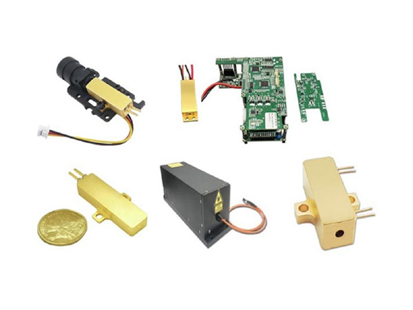

High Power, High LIDT Laser Optics
Understanding optics for high power lasers
INTRODUCTION
All of us who work with power lasers have experienced laser damage, usually when we least wanted to. That flash of light in our darkened firing labs or audible “pop” signals that the day has just got a bit longer. Catalog optics are fine for many laser applications but high power lasers require specified damage characteristics of their optics.
Laser Evolution
A meteoric expansion of laser applications has resulted in lasers becoming more and more powerful. Laser applications range from space photonics down to the more terrestrial based life sciences and surgical tools. The technology responsible for enabling this expansion is optical coating technology. Basically, this means there can be no increase in laser power if the component coatings are not up to the damage threshold required and in the past decade there has been a step function upgrade in coating technology using low-defect techniques for deposition, substrate polishing, substrate surface pacification and cleaning. Many of these highly controlled clean technical techniques were initially developed for microelectronics fabrication.
What is Coating Technology?
The highly transparent plate glass in windows can be made totally reflective by applying a metal coating to it. Architectural plate glass changes from near totally transparent to totally reflective by applying a metal coating to it.
Sadly, metal coatings have very low damage thresholds so all power lasers contain dielectric mirrors. However, there are 1000s of different types of dielectric coatings, changing properties of the substrate to: anti-reflective (AR); highly reflective (HR); all manner of partial reflectivity; polarizing optics; long and short pass filters and many more. Most substrates are glasses but crystal substrates are also used for waveplates and non-linear optics for frequency doubling and tripling. Moreover, all the above are available at a plethora of wavelengths that can range from the UV out to 10 µm and beyond.
Coatings are seldom a single layer. Complex filters can have many 10s of coatings applied to specify their application. Coating technology is highly advanced and jealously guarded as all advances have come with a high price tag due to the complexity of the amorphous nature of the coating.
Coating processes are complex and rely on having substrates that are uniform in terms of composition, transmission and refractive index. The uncoated substrate surface must be free from stress (polishing induced) defects; clean; and in some cases, a reactive surface is required. Grinding, polishing, defect removal, stress relief, cleaning and surface conditioning of the substrates all can be considered part of coating technology.
POWER RESILIENCE OF LASER OPTICS – LIDT
Damage thresholds are determined in terms of peak pulse power density. The threshold is the point at which further increase in power density can result in damage. The methods used are detailed rigorously in several ISO standardsi governing Laser Induced Damage Threshold (LIDT) determination. Laser damage is defined as "any permanent laser-radiation-induced change in characteristics of either the substrate or the coating". We often assume that it is only pulsed laser optics that require damage testing as CW testing is perhaps less than 2% of the volume tested due to their relatively low power applications (we exclude CO2 lasers here). And we may also be forgiven for assuming the nanosecond regime is the bee’s knees, as pulsed lasers in the nanosecond regime account for well over 90% of the current power market. However pico- and femtosecond applications are also growing.
When a coating is damaged inside a laser resonator, we can see a cascade of damage and identifying which optic started the process can be tricky. Damage during laser manufacture and more worryingly during operation can be immensely costly and downgrades customer confidence. Laser damage testing is essential for many applications.
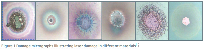
The advantage for the consumer (either an optical designer or a component manufacturer) of working with an independently validated, commercial testing firm is above all accuracy. Consistency and accuracy can avoid the types of damage shown in Figure 1.
The system developer is well-advised to send samples out on a “round robin” assessment of testing facilities – to find out the level of detail and analysis provided. Most large volume power laser manufacturers (end users) will have a preferred test house providing consistent results. LIDT reports should give the coater more information than just a number. Advanced analytical threshold determination methods can reveal important damage diagnostics. Testing provides a low-cost route to coating development.
ISO Standard Damage Test Types
ISO 21254-1,2 and 3 Standards define the test methods for determining the laser-induced damage threshold and for the assurance of optical laser components subjected to laser radiation as well as the vocabulary and definitions related to laser induced damage.
All damage tests are statistical tests and sample sizes over 15 mm2 allow the best test outcomes. ISO 21254-2 describes the methodology of the tests. There are two principal tests: S-on-1 and 1-on-1.
S-on-1 refers to several shots on each unexposed test site. Some materials require many 100s of hits per site. An array of test sites gives the statistical damage information over the sample surface.
1-on-1 refers to a single shot on each unexposed test site; each shot is on a fresh site. This test is used where subthreshold annealing or sputtering cause inaccuracy.
So why can we not just use a single site and ramp up the power to find the threshold? Two reasons: first the chosen site may not represent the entire surface, and secondly, sub-threshold irradiation anneals the sample raising (falsely) its LIDT by a substantial amount.
MEASURING LIDT
Threshold Determination
LIDT tests are used in process evaluation and in some cases coater evaluation. It reveals actual threshold values in MW/cm2 (or J/cm2 specifying the pulse duration). The most common, and by far the most rigorous test for the sample is the ISO 21254-2:2011; S-on-1 testiii. Several shots are applied to each site.Figure 2 shows a typical test pattern and an idealized damage pattern. Damage testing is a statistical process, variations over the surface are accounted for by testing several rows located over the surface. Each site within a row gets the same energy or power. This is increased row by row.
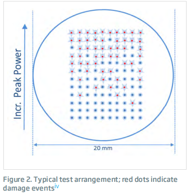
Incident sites (usually well over 100 sites) are exposed to the beam.
Each site is exposed to several pulses for a standard S-on-1 test.
Each site in a row is tested at the same power level. Power is increased, row by row until a damage pattern is obtained.
The peak power level is the critical factor in causing damage.
The idealize pattern shown above would produce the “perfect” graph, shown in Figure 3.
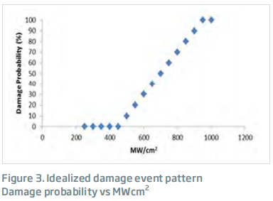
Graphical Analysis. The very first damage events are the most difficult to detect. The threshold is obtained from the intersect. And so, graphing the results removes the uncertainty of missing that first event. Graphical analysis also provides coating uniformity information
Least Fluence only gives the last value at which no damage was detected.
Certification Pass/Fail Tests
After a level of confidence is gained in the process via threshold tests, batch-to-batch consistency can be monitored by Pass/Fail certifications. Here “user defined” specification stipulates an acceptable end user value and several sites within a central area of the test piece are irradiated at that value. This provides a low-cost route to ongoing process evaluation and reproducibility.
Spot Size (Beam Diameter)
Spot sizes of 0.8 to 1.00 mm are ideal. Spot size can become an issue when the test laser power is limited. ISO 21254-1:2011 sets a lower limit for beam diameters of 0.2 mm. Below the 0.2 mm limit accuracy is severely compromised. LIDT and Pulse Duration Regimes Nanosecond Regime: Most high-power lasers and laser systems inhabit the nanosecond regime. This class of lasers is used in space applications; target designation, metal machining and surgery. Eye and angioplasty surgery are laser controlled to achieve the accuracy needed and where a low zone of necrosis is essential. LIDT damage mechanisms within this regime are fundamentally heat based and a high level of accuracy is possible in these measurements.
Picosecond and femtosecond: As we get smaller and smaller pulse durations the high-power applications shift from metal machining to the much more difficult glass machining applications. Laser damage mechanisms change gradually through the picosecond to the femtosecond regime; electric field plays an increasing part in damage mechanisms and is an increasing contributor to damage causation. Early work in 1972v first saw that the electrical field was a contributor. One of the restrictions in femtosecond laser design and subsequent growth originates from a lack of accurate femtosecond laser damage. The corona of charge contributes to lowering the LIDT.
Defects from structural features
Transparent and semitransparent materials are most susceptible to laser damage as the beam passes through the material. It has more opportunity to cause damage than say in mirrors, where the beam will penetrate only a few microns into the dielectric coating. LIDT can be lowered by physical defects arising from:
Non-perfect surface finish: The polishing process limits the surface threshold of laser induced damage by introducing (or not removing) various imperfections: roughness, scratches, pits, microcracks, impurities, and where applicable, crystal dislocationsvi.
Inclusions: Inclusions larger than 0.1mm in diameter will absorb the laser energy, heat, and cause mechanical failurevii.
Defects -from molecular absorbers; electronic states in the band gap
For most high LIDT optics manufacturers a low physical defect structure is the starting point. Now comes the true nitty gritty of high end optics: Damage due to submicron defects and absorbers. We now take a step into the science behind high laser threshold damage and why it is essential to conduct an LIDT test at the optic’s specified wavelength.
LASER DAMAGE CAUSES
What is a defect? Multi-disciplinary ways of telling the same story
Coatings are thin film amorphous structures and development of optical coatings is in practice the domain of optical coating technologists. Development of different compositions and substrates is, by definition, the realm of solid state chemists and more recently of material scientists. But the end users of high-end optics are physicists and so the language of damage oscillates from one to the other. What a chemist will call a dangling bond, a physicist will tag as a defect state or localized defect state. All are correct. The physicist’s energy diagram of defect states can predict wavelength-specific damage as can the chemist’s FTIR spectroscopy of the region of interest. Both approaches give helpful insights.
Glasses and their LIDT sensitive interactions
Many problems exist in the glassy (amorphous) state that are more easily dealt with in crystals. For example; all glasses have additional “tail states” at the edge of the band gap compared to their crystal counterpartsviii. Tail states originate from the frozen-in structure of glass (distorted bond angles and bond lengths). But there are also defect states within the band gap due to dangling bonds, non-stoichiometric local content and unsaturated bondsix. Optics manufacture is all about ridding the structure of these states to allow absorption-free pathway through the glass, the coatings and all the interfaces present. This is certainly a challenge for the coating manager. Extensive work has resulted in High-LIDT laser optics and in turn high power lasers.
Coatings are designed for specific wavelengths and at the wavelength of use they are fabulously clear of defects; 99.95% transmission is common in high LIDT AR optics and that is the overall figure including all interfaces. If there is a known absorber within the desired wavelength region great care must be taken to exclude that absorbing species.
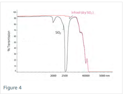
Water or -OH in glass and its effect on laser damage thresholds
If we look at fused silica, as it is the most common substrate, and the most robust, it has a wide band application with cut offs above 175 nm and the IR at over 2800 nm. Its major absorbing species is the -OH stretch shown in Figure 4. The main absorber problem in the near infrared (NIR) is the -oxygen hydrogen (-OH) bond. We know that the -OH bond has a resonance at 2 µm (stretch) and another just prior to its cut off at about 3 µm (deformation). But these absorptions can be very broad and start affecting LIDT values at about 1400 nm. So, what is happening?
Two effects contribute to the extensive -OH absorption. The first is thermal, the fundamental stretch frequency peaks at about 2000 nm and when 2 µm laser light passes through, energy is absorbed from the beam to cause stimulated vibration in all -OH species present. Another process contributes; the energetics of the -OH bond vibration. The easiest opportunity to break the -OH bond is at full extension or at full compression, i.e. at each end of the vibration. The resonance frequency absorption increases the opportunity as the number of vibrations increase. So, we have a twofold mechanism for accelerating damage and reducing the optic’s LIDT value.
RESEARCH & DEVELOPMENT
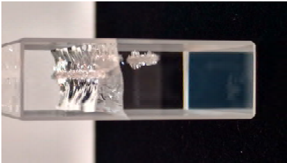
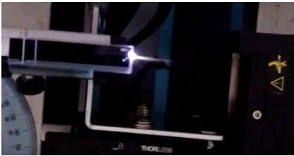
An ongoing research project by our independent test house, Belford Research, into novel 2-micron testing methods threw up some extraordinary live footage of damage enabled by high quality G&H coatings.
This Figure shows a high threshold G&H front face coating allowing an intense laser beam to enter a silica block. The beam was so intense that the Kerr Effect was evident and explosive damage is seen happening live on the exit face.
For this event to occur the high quality of the coating actually elevated the surface damage threshold of Silica by ~30%. While this is seen frequently in low LIDT substrates, we have never seen this in silica. Uncoated fused silica has a very high damage threshold.
BEST PRACTICES TO ACHIEVE HIGH LIDT COATINGS
Particles, scratches, and impurities smaller than a fraction of a micron will generate large craters of damage when subjected to intense, short-pulse radiation. Surface features can cause refraction and interference giving all manner of damage patterns. Defects which do not impair performance of a vision system can easily cause a failure in a laser radiation environment. A good review of the current state of the art in 2015 is Laser-Induced Damage in Optical Materials by D. Ristaux.
To achieve High LIDT Optical Systems, the designer needs: finished substrates with minimal defects; cleaning processes which enhance the bond between coating and substrate, and most importantly coating designs that minimize absorption, enhance durability, and optimize beam qualities. The assembly needs to be robust and protect the optical components from outgassed materials and particulate accumulation.
Pursuit of Perfect Substrates
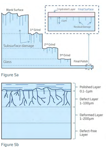
Optical component fabrication comprises several mechanical steps to shape, grind, and polish the substrate into its predetermined form. Each mechanical step will generate stress and strain on the optical surface, damage the subsurface, imbed impurities from polishing materials, weaken the surface with a sub-ideal pH and create defects in the glass (or crystalline) optical substrate.
Figure 5a is a schematic view of successive steps from shaping to polishing. Figure 5b gives the mechanical damage depths in microns.
Providers of high power optical systems employ a variety of inspection tools to ascertain the true surface quality. High LIDT optical fabricators, such as Gooch&Housego, work closely with their slurry suppliers to create the ideal physicochemical polishing environment. Too acidic a slurry will create an “orange peel” effect, too basic and the material removal rates can be reduced to become non-effective. Sub-substrate damage, SSD, is caused by the several mechanical forming and polishing steps. SSD can be minimized by a gradual decrease in polishing particle size, removing enough material to eliminate the fractures from the previous step.
Requirements for even higher levels of cleaning utilize remote plasma etching to give a contact-free final step. Various non-destructive testing methods have been developed to identify SSD including optical coherence tomography, total internal microscopy, confocal fluorescence microscopy, and light scatteringvi. Post-polishing treatments with laser annealing, acid etching, and MRF finishing have all proven to be effective at reducing the surface defects and improve LIDTvi.
Perfection in Cleaning
Cleaning involves two primary steps. The first is to remove all particulates and organic contaminants from the surface. The second is to generate a chemical environment which facilitates or enhances the bond between coating and substrate. High LIDT coating providers are naturally wary of accepting substrates polished and cleaned in a third-party facility.
First, they must thoroughly re-clean the substrates and assume a wide variety of contaminants are deposited upon the optic. As they inherit the polishing process physicochemical environment (acidic, basic, slurry materials, and subsurface damage).
Secondly, hand finishing or advanced ultrasonic cleaning can create an ideal surface to coat.
Optimized Coating Equipment
High LIDT coating facilities follow stringent procedures to minimize contamination from all sources, an ISO 14644-1 class 2 clean-room environment is used for high power optical coating. Everything is specified, from oil-free vacuum pumps, to the type of deposition electron guns and targets. All planetaries, targets, guns and sources are designed or specified along with material sourcing.
There is an extensive variety of high LIDT components; windows, mirrors, prisms, beamsplitters, polarizers, and filters. Each with its own unique requirements for high LIDT – chambers become optimized for certain types of coatings and each chamber is customized to serve a subset of optical coatings and wavelengths. Deterministic metrology is used during coating to deposit the correct amount of each material at each layer. Interferometry, spectroscopy, and polarization testing are all carried out very near to the coating chambers to ensure compliance with specifications without leaving the clean coating environment prior to packaging.
DESIGNING NEW COATINGS
Nothing can replace the experience and talent of our top coating designers in whose hands, these precision processes are used to bring coatings into existence. Creating a new coating is an iterative process. It is a balancing act of combining coating methods, chemical composition, deposition timings and rates. They finally yield an index-matched, defect free, high damage tolerance optic to modulate, twist, polarize, reflect or transmit high intensity short pulse laser power. A challenging set of requirements and one indicative of the complexities of the optical manufacturing and the application processes. The number of iterations in a new coating design can be markedly reduced by high quality, highly consistent LIDT testing, showing the direction of change.
MAINTAINING STANDARDS
The magic wielded by the talented coating technologist must be repeated day in, day out. Once your standards are known in the high-energy market, they have to be delivered every time.
Repeatability
Regular testing of the coated optical components during the design process and after ensures not just compliance for a particular batch of optical components, but also that the day-in/day-out operations of the coating facility are repeatable and reliable. Followers of the Deming quality system know that a process which is under control stays within its operating conditions all the time. Gooch & House go therefore, strives to ensure its coating systems operate within control with continuous testing of coated optics. Few companies can boast the reputation G&H has for consistent high quality.
Accuracy
G&H’s process testing accuracy removes the uncertainty which often besets extrapolation. Witness testing of substrate-coating system G&H witness testing pieces are from the same polishing batch, cleaned at the same time, and coated in the same orientation and can be the same shape, as the actual production parts. Witness pieces are tested regularly to ensure high LIDT and confirmation of coating processes and the entire coating-substrate system. Few competitors can boast these standards.
Insertion Loss testing
More complex optical components, such as Q-switches, are tested by G&H for insertion loss. An at-wavelength laser insertion loss test is a good predictor of LIDT performance and component longevity. High insertion loss is a good indicator of absorption or scattering – both of which lead to failure modes for pulsed applications. At-wavelength laser testing of Insertion Loss also provides an excellent source of coating performance feedback. This further improves process improvements in the coating methods and procedures.
Absolute Performance
Direct, at-wavelength measurements and regular testing lead to a continuous process improvement cycle for any manufacturer of high LIDT components. Through their adherence to best-in-class processes and in-house development, G&H has realized coating processes which consistently result in some of the highest LIDT across all coating materials; It has actually significantly increased the LIDT value of the robust polished quartz surfaces; and doubled the LIDT value of some softer bulk materials.
In The Pipeline
Each new laser application, whether it be new wavelengths; smaller pulses; higher powers; frequency modulating and or wavelength tuning, all without exception owe their possible existence to better, stronger, higher LIDT coatings.
Within four years of the first laser being fired in 1960, it was reported in the literature that “laser damage to optical coatings was inhibiting further development of higher powered lasers”. And this still holds true. Coating technology is the enabling technology for the entire laser industry. LIDT testing is the guide for new coatings development.