 English
 Français
 Deutsch
 euskara
 Русский язык
 Italiano
 Português
 Nederlands
 Polski
 Greek
Greek Lietuva
 Türkçe
 日本語
日本語 한어
한어 中文
中文 தாமில்
 فارسی
فارسی हिंदी
हिंदी Tiếng Việt
 ภาษาไทย
 Pilipino
 Indonesia
 தாமில்

Continuous operation of a coherent 3,000-qubit system
Neutral atoms are a promising platform for quantum science, enabling advances in areas ranging from quantum simulations and computation to metrology, atomic clocks and quantum networking Although atom losses typically limit these systems to a pulsed mode, continuous operation could substantially enhance cycle rates, remove bottlenecks in metrology and enable deep-circuit quantum evolution through quantum error correction. Here we demonstrate an experimental architecture for high-rate reloading and continuous operation of a large-scale atom-array system while realizing coherent storage and manipulation of quantum information. Our approach utilizes a series of two optical lattice conveyor belts to transport atom reservoirs into the science region, where atoms are repeatedly extracted into optical tweezers without affecting the coherence of qubits stored nearby. Using a reloading rate of 300,000 atoms in tweezers per second, we create over 30,000 initialized qubits per second, which we leverage to assemble and maintain an array of over 3,000 atoms for more than 2 hours. Furthermore, we demonstrate persistent refilling of the array with atomic qubits in either a spin-polarized or a coherent superposition state while preserving the quantum state of stored qubits. Our results pave the way for the realization of large-scale continuously operated atomic clocks, sensors and fault-tolerant quantum computers.
Recent experiments have enabled continuous atomic and optical clocks, as well as the realization of continuous Bose–Einstein condensation. Although past efforts have primarily focused on controlling atomic ensembles, most recently these techniques have been extended to explore continuous operation with individual atom control. If expanded to high reloading rates within a coherence-preserving setting, these pioneering experiments highlight the exciting possibility of fully continuous operation of large-scale atomic systems.
Here we introduce a tweezer array architecture that enables such coherent continuous operation at large scale with reloading rates of up to 30,000 qubits per second, nearly 2 orders of magnitude above the current state of the art. Our architecture is based on two serial optical lattice conveyor belts that transport a cloud of laser-cooled 87Rb atoms into the field of view of our microscope objective. From this reservoir cloud, atoms are loaded into optical tweezers ‘in the dark’ (that is, without laser cooling) and then repeatedly extracted into a ‘preparation zone’, where they are laser-cooled, imaged, rearranged and initialized into their qubit states. Once initialized, atomic qubits are then transported and iteratively assembled into a large array in the ‘storage zone’, where dynamical decoupling is applied to maintain qubit coherence. Qubits in the storage zone are spatially protected against scattered cooling light by avoiding direct line of sight to the magneto-optical trap (MOT), and spectrally protected by light-shifting the cooling transition out of resonance (‘shielding’). We demonstrate in situ atom replenishment and maintenance of more than 3,000 storage array atoms for more than 2 hours, well beyond the trap lifetime of about 60 seconds. Furthermore, we sustain the storage zone with either spin-polarized qubits (Z basis) or qubits in the equal superposition state (X basis) for, in principle, unlimited duration.
High-rate reloading from a lattice reservoir
Our dual-lattice architecture is designed for uninterrupted high-rate qubit reloading that enables repetitive usage and periodic replacement of an atomic reservoir (Fig. 1a). The experiment starts by loading around 4 million 87Rb atoms from a MOT into an optical lattice conveyor belt. Then, the atom cloud is transported through a differential pumping tube to the separate science chamber, where it is transferred to a second lattice conveyor belt and delivered into the microscope field of view to serve as an atomic reservoir (Extended Data Figs. 1 and 2). Using this two-stage procedure, a fresh reservoir of 2.5 million 120-μK cold atoms arrives in the science region every 150 ms. From the lattice reservoir, atoms are repeatedly loaded into a dynamic optical tweezer array of 120 × 12 sites, generated by a pair of crossed acousto-optic deflectors (AODs; Extended Data Fig. 3). To load atoms, we switch on the AOD tweezers overlapped with the lattice reservoir and immediately transport captured atoms into the preparation-zone region placed 220 μm above. This procedure takes less than 2.5 ms and, importantly, allows for multiple extraction cycles from a single reservoir. Following the extraction, atoms in AOD tweezers are transferred to a static tweezer array generated by a spatial light modulator (SLM).
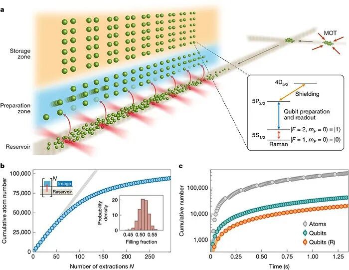
a, A cloud of laser-cooled atoms is transported over 0.5 m from a separate MOT region into the science region via two optical lattice conveyor belts crossed at an angle. In the science region, the optical lattice serves as an atomic reservoir, from which a two-dimensional array of optical tweezers repeatedly extracts atoms into the ‘preparation zone’. Here, atoms are laser-cooled, rearranged into a defect-free array and their qubit state initialized, then transferred into a large-scale storage tweezer array (‘storage zone’). Our dual-lattice scheme avoids direct line of sight between the tweezer arrays and the MOT location, and enables fully concurrent preparation and replenishment of the atomic reservoir. Inset: relevant atomic levels of 87Rb, where F denotes the hyperfine level and mF the magnetic sublevel. During qubit preparation, storage qubits are protected from near-resonant photon scattering with the 5S1/2 → 5P3/2 transition by light-shifting the excited state (‘shielding’). Single-qubit gates are implemented via optical Raman transitions that drive clock states and (Methods).
b, Cumulative number of atoms obtained by N-repeated tweezer extractions from a single lattice reservoir (see top-left schematic), where we observe a decline in tweezer filling fraction after about 70 repeated extractions owing to reservoir depletion (see also Extended Data Fig. 4). For reference, the grey line indicates 50% array filling. Inset: histogram of tweezer filling fractions for the first 30 extractions from the reservoir. Notably, no laser cooling is applied during the tweezer loading process. c, Cumulative number of atoms and qubits obtained by tweezer extraction from repeatedly replaced lattice reservoirs. The grey markers indicate an atom flux of about 300,000 atoms per second after light-assisted collisions, where the brief interruptions originate from the second transport stage of reservoir replacement during which no reservoir is present. Performing the qubit preparation sequence after each extraction, we achieve a continuous qubit flux of 15,000 qubits per second with rearrangement (R; orange) and 30,000 qubits per second without rearrangement (green). Error bars represent the standard error of the mean across 10 repetitions.
Figure 1b shows the results of repeated tweezer extraction from a single lattice reservoir. Here, we extract atoms for multiple cycles and only image and count single atoms after the final extraction cycle, and quote the cumulative number by summing the atom counts over all N cycles. We find that, initially, array filling fractions of >50% are comparable to conventional tweezer loading from an MOT40, but gradually decline as the reservoir is depleted (see also Extended Data Fig. 4). A key aspect of our dual-lattice design is the ability to extract atoms from one reservoir while preparing and delivering a fresh reservoir to the science chamber. By replacing reservoirs as they are depleted, this approach overcomes capacity limits of any single reservoir. In Fig. 1c, we demonstrate this by repeatedly extracting atoms into the preparation zone as before, now replacing the reservoir every 60 tweezer loading cycles. As a result, we achieve a flux of approximately 300,000 atoms in tweezers per second, corresponding to the maximum rate at which reservoir atoms can be extracted.
Notably, in contrast to the conventional approach to tweezer loading40, no laser cooling is applied during the extraction process. We attribute the ability to load optical tweezers ‘in the dark’ to a combination of stochastic overlap with atoms in the reservoir, and atomic collisions similar to the notion of a dimple trap41 (Methods). Whereas previous experiments17,18,19 have relied on dissipative laser cooling or tweezer-lattice intensity ramps when loading fresh atoms from the reservoir, our scattering-free method helps preserve coherence of nearby storage qubits and avoiding lattice ramp-down enables repetitive usage of the reservoir.
To prepare atomic qubits, we perform an initialization procedure after every extraction from the reservoir (Extended Data Fig. 5). Each step of this procedure relies on two counter-propagating laser beams local to the preparation zone and aligned coaxially with an externally applied static magnetic field24 (Methods). First, an explicit parity-projection pulse via finite-field polarization gradient cooling on a red-detuned F = 2 → F′ = 3 transition prevents multiply occupied optical tweezers. Here, F denotes the hyperfine level of the atomic ground state and F′ the hyperfine level of the 5P3/2 excited state. We continue laser cooling via polarization gradient cooling during AOD-to-SLM handover, then apply a resonant push-out pulse to eliminate atoms in out-of-plane traps10. This is followed by high-contrast, inherently background-free imaging (Methods). Afterwards, we arrange atoms into a defect-free array while further laser cooling via electromagnetically induced transparency with light blue-detuned from the F = 2 → F′ = 2 transition42. Finally, atoms are initialized to the qubit state by optical pumping on the F = 1 → F′ = 0 transition, resulting in a state preparation and measurement fidelity of approximately 98% within 20 μs. Under optimal conditions and without atom sorting, the qubit preparation sequence takes 20 ms (Methods).
Figure 1c shows the results of repeatedly extracting atoms and performing the qubit preparation sequence as described above, while the lattice reservoir is replaced in parallel every few tweezer extraction cycles. As a result, we achieve a qubit flux of over 30,000 qubits per second when choosing to not rearrange atoms. With atom sorting, the qubit preparation time approximately doubles and we obtain up to 15,000 qubits per second, rearranged into defect-free batches of 600 qubits. In all cases, the qubit preparation time exceeds the time required for the second transport stage of reservoir replacement; as such, there is always a reservoir present for tweezer extraction and the qubit flux is uninterrupted.
Assembly and maintenance of a large atom array
After the preparation sequence, the rearranged array is transported to the storage zone, which consists of 3,240 (90 × 36) SLM-generated optical tweezers with an average trap depth of 270 μK. The storage tweezer array features alternating regularly spaced columns for lossless atom transport in between (Methods), and is positioned with sufficient distance to the preparation zone and the lattice reservoir to limit crosstalk between zones (Fig. 2a).
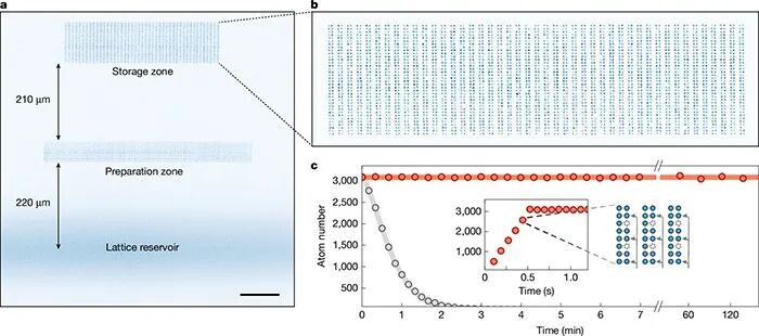
a, Atom fluorescence image outlining the zone architecture consisting of a lattice reservoir, a 1,440-site preparation zone, and a 3,240-site storage zone. (Averaged) images of each zone are exposed separately and combined with different weights for visualization purposes. Scale bar, 100 μm.
b, Single-shot fluorescence image of 3,217 atoms in the 3,240-site storage array (99.3% filling). c, Iterative construction and continuous maintenance of a large-scale atomic array. Initial assembly occurs in 0.5 seconds via 6 loading iterations (inset). Afterwards, one of six segments (‘subarrays’) is ejected from the storage array and refilled with a fresh set of atoms every 80 ms (see also Extended Data Fig. 6 and Supplementary Video 1). Here we show cyclic subarray replenishment and continuous maintenance of a 3,000+ atomic array for over 2 hours of operation, far beyond the tweezer-limited lifetime of about 60 seconds (grey). At the final data point, t = 2.3 h, over 50 million individually imaged and rearranged atoms have been cycled through the storage array. Error bars represent the standard error of the mean across 10 repetitions.
We assemble the storage array in six iterations, each time transferring atoms into one of six segments (‘subarrays’) interspersed throughout the storage array (Extended Data Fig. 6). Preparation and loading of each subarray, including atom transport to the storage zone, takes roughly 80 ms (mostly limited by rearrangement time and image data transfer). Assembly of the entire storage array is completed in about 500 ms with an averaged loading of 3,193 atoms (98.5% filling fraction) over 300 trials. Figure 2b shows a single-shot fluorescence image of 3,217 atoms loaded into the array.
In Fig. 2c, we demonstrate the ability to maintain over 3,000 atoms in the storage array for over 2 hours of continuous operation. After initial storage array assembly, we sequentially eject and refill the longest-stored subarray with a concurrently prepared set of fresh atoms from the preparation zone (Supplementary Video 1). In parallel to atom preparation and subsequent replenishment, we replace the lattice reservoir every other tweezer extraction cycle without affecting the storage-zone array. Using these techniques, we replenish atoms on much faster timescales than their tweezer-limited lifetime, and therefore enable operation that is, in principle, indefinite.
Coherence during continuous operation
The ability to reload qubits while preserving the coherence of existing qubits is essential for applications in deep-circuit quantum computation and high-bandwidth metrology. To address this challenge, in Fig. 3a we first investigate the impact of a simultaneously operating MOT on storage qubit coherence. We observe a coherence time of T2 = 1.15(3) s when applying dynamical decoupling in the presence of the distant MOT, which shows minor modification compared with a reference measurement without the MOT (T2 = 1.34(4) s). In Fig. 3b, we find a similar result when probing the storage qubit depolarization time T1 with and without the MOT. Therefore, by preventing a direct line of sight between MOT and qubits, our angled dual-lattice transport scheme successfully disentangles the scattering-intense initial capture of an atomic gas from parallel quantum operations.
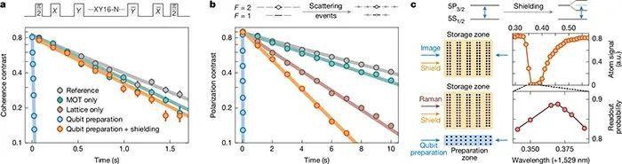
a, Coherence contrast under various conditions when applying N repetitions of an XY16 dynamical decoupling sequence with π-pulse spacing 2τ ≈ 1.6 ms to storage qubits, where the reference measurement yields T2 = 1.34(4) s (grey). Operating the distant MOT in parallel to dynamical decoupling, we observe a minimal effect on coherence (green) compared with the reference, but a strong effect when additionally imaging in the preparation zone (blue). By applying qubit shielding, we restore coherence almost fully (orange, T2 = 1.09(3) s).
b, A similar comparison probing depolarization of qubits initialized in with the reference measurement T1 = 12.6(1) s (grey), consistent with Raman scattering calculations owing to the tweezer light51. Although operating the MOT simultaneously has a negligible effect on storage qubits (green), additionally imaging in the preparation zone results in rapid qubit depolarization (blue). Similar to before, this can be mitigated by shielding storage qubits from near-resonant light (orange, T1 = 3.43(3) s), mainly limited by off-resonant Raman scattering from the lattice light to which the shielding is ineffective (brown). A similar investigation for state depolarization along with all measured T1 and T2 times is presented in Extended Data Fig. 8. For a and b, the difference of qubit populations measured in and provides the contrast (Methods).
c, Shielding light spectroscopy on storage qubits. First, we image the storage array while applying low-power shielding light at variable wavelength to resolve the 4D5/2 resonance by suppression of imaging signal (top). In a fine scan, we optimize for storage qubit coherence under dynamical decoupling while imaging in the preparation zone by maximizing the readout probability in (bottom). Error bars represent the standard error of the mean across 10 repetitions.
In addition to the MOT, the coherence of existing qubits can be affected by scattered light and magnetic-field changes during mid-circuit qubit preparation. To mitigate this, our beam architecture operates under constant finite magnetic field24 and is localized to the preparation zone. However, we initially observe in Fig. 3a that storage qubit coherence is strongly affected by beam crosstalk during the preparation-zone imaging procedure. To suppress this effect, we protect qubits from near-resonant scattering by light-shifting the excited state35 of storage-zone qubits as shown in Fig. 3c (see also Extended Data Fig. 7), and find that the coherence time can be nearly completely restored (T2 = 1.09(3) s). In addition, we probe storage qubit depolarization under the same conditions in Fig. 3b, resulting in a similar conclusion. Here, however, one observes an increased T1 decay compared with a reference measurement despite shielding, which is largely dominated by off-resonant scattering from the lattice reservoir light (Extended Data Fig. 8). This increase does not measurably affect our T2, but can be further mitigated by, for example, greater reservoir distance from the storage array, smaller lattice reservoir waist or larger lattice detuning.
Building on these results, we now assess atom-loss replenishment in simple quantum circuits by repeatedly replacing storage-zone qubits while maintaining coherence. In Fig. 4b, we first show high-rate reloading and continuous maintenance of a large array of spin-polarized storage qubits. Similar to Fig. 2c, we now repeatedly prepare freshly initialized qubit subarrays in the preparation zone, then eject and refill the oldest subarray in the storage zone as shown schematically in Fig. 4a (see also Extended Data Fig. 9). Sequentially replenishing qubits allows us to sustain a high degree of storage array polarization for, in principle, unbounded duration; here, we show maintenance of over 3,000 qubits for 2 minutes.
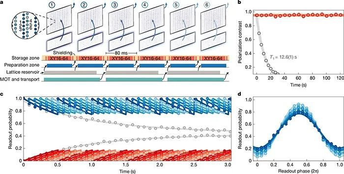
a, Time sequence visualizing our reloading protocol (see also Extended Data Fig. 9 and Supplementary Video 1). Following the initial storage array assembly, the longest-stored subarray is ejected and refilled with a preloaded set of qubits from the preparation zone every 80 ms, whereas storage-zone shielding is applied throughout. For c and d, storage qubits are placed in the equal superposition state and undergo an XY16-64 decoupling sequence during each reloading cycle.
b, Sequentially replenishing storage-zone qubits, we maintain a high degree of storage array polarization (red) for, in principle, unbounded duration. For reference, we provide a T1 measurement without qubit replenishment (grey).
c, Similar to b, now additionally applying an Xπ/2 − (XY16-64) − X−π/2 dynamical decoupling sequence during each subarray replenishment. We probe coherence of each subarray at various times during the replenishment cycle by reading out qubits in state (blue) or (red) as detailed in Methods. Individual subarrays (colour shading) are unaffected by adjacent qubit reloading, and their dephasing is offset in time due to the cyclic subarray reloading protocol. The exponential sawtooth overlays are guides to the eye. For reference, we provide the T2 measurement of a single subarray under the same cyclic decoupling sequence without qubit replenishment (grey).
d, After multiple rounds of reloading under dynamical decoupling, we apply a final dynamical decoupling sequence and vary the phase of the last π/2 pulse to read out in different qubit bases. Complementary to c, the observed coherence contrast varies for each subarray (colour shading) owing to the time offset in subarray replenishment. Error bars represent the standard error of the mean across 10 repetitions.
Finally, in Fig. 4c,d, we show the ability to reload and sustain a large array of atomic qubits in a coherent superposition state (see also Extended Data Fig. 10). While shielding and replenishing qubits as in Fig. 4b, we additionally rotate storage qubits into state and sustain coherence by applying a dynamical decoupling sequence during each subarray reloading cycle. Shortly before replenishing a qubit subarray with fresh qubits from the preparation zone, we map coherence into population by rotating all storage qubits into state , eject and replace the oldest qubits with newly spin-polarized ones, then rotate back into state as a new reloading cycle starts. This enables us to keep qubits in a superposition state at about 90% duty cycle, with the coherence of individual subarrays unaffected by concurrent reloading cycles.
Discussion and outlook
Our experiments demonstrate an atom-array architecture that enables continuous operation with reloading rates of up to 30,000 initialized qubits per second while preserving coherence across a rearranged large-scale qubit array. The results can be extended along several directions. First, the qubit preparation time can be substantially shortened through optimized readout and the use of field-programmable-gate-array-based and/or artificial-intelligence-optimized rearrangement protocols45,46. Second, larger preparation-zone arrays can be engineered by fully utilizing the system’s optical field of view. We estimate that these technical improvements would lead to a more than fivefold increase in qubit reloading rate, as this rate is directly proportional to qubit preparation time and preparation-zone size. In addition, although the present experiments demonstrate continuous operation for over 2 hours, achieving much longer operation would benefit from active stabilization of the SLM–AOD tweezer overlap or automated beam alignment procedures. Finally, higher-power trapping lasers and high-efficiency diffractive optics, such as metasurfaces47, can be immediately deployed to scale the storage and preparation-zone size, supporting continuous operation of tens of thousands of atomic qubits.
Our results open up a range of scientific opportunities based on atom-array platforms. In particular, our method is directly compatible with a zoned architecture for quantum computation involving Rydberg-mediated entangling gates, local optical Raman control and dynamically reconfigurable qubit arrays. This architecture therefore presents a promising approach towards the implementation of deep, fault-tolerant quantum circuits using error correction. In a complementary experiment conducted in a separate apparatus, we demonstrate the core components of such a fault-tolerant quantum processor, including a method for mid-circuit loss-resolving qubit readout and re-use as well as deep-circuit protocols involving logical qubit teleportation, below-threshold repeated error correction and universal fault-tolerant processing. Atom losses have a major role in these experiments, and the ultimate circuit depth is directly limited by atomic reservoir depletion.
Taken together, our experiments open the door for realizing large-scale error-corrected quantum processors. For example, accounting for the current entangling gate fidelity (approximately 99.5%) and atom-loss rate, at a 1-ms duration per gate layer, we estimate that 15,000 rearranged qubits per second should be sufficient to replenish lost atoms in a quantum processor with about 10,000 physical qubits. Furthermore, realistic improvements in entangling gate fidelities to approximately 99.9% and reloading flux to 80,000 qubits per second could enable the operation of several hundred surface code logical qubits with a logical failure rate down to 10−8 . Moreover, the natural compatibility of this architecture with high-rate quantum low-density parity check codes will probably unlock further improvement in quantum processor performance.
Beyond applications in quantum computation, a continuously operating atom-array system could overcome several limitations in quantum metrology, enabling high-bandwidth and entanglement-enhanced precision quantum sensing. Furthermore, a continuous stream of atomic qubits is essential to achieve fast generation of remote entanglement in quantum networking applications. Finally, our high-rate reloading scheme and the transition from pulsed to continuous operation that it enables may be utilized to improve the performance of a broad class of cold-atom experiments, including quantum simulation, sensing and precision measurements.
Vacuum system
A simplified schematic of our vacuum system is shown in Extended Data Fig. 1a. The system consists of an MOT chamber and a science chamber, separated by a custom-designed differential pumping tube (DPT; Limit Vacuum Technology) with a 1.5-mm back aperture and 4.3-mm front aperture. The DPT maintains a pressure differential between the two chambers and blocks most of the MOT light. Both the DPT and the MOT chamber are tilted by approximately 4° to prevent direct scattering of cooling light onto the atomic array in the science chamber, where the line of sight passes about 1 cm above the array location. The MOT chamber is primarily composed of a glass cell (Precision Glassblowing) with two rubidium dispenser arms (not shown in Extended Data Fig. 1). The science chamber features a double-sided antireflection-coated glass cell (Akatsuki Technology) with optical contact technology. In both chambers, the pressure remains below the measurable threshold of the ion pumps (SAES NEXTorr and Agilent StarCell 75). Several components are omitted from the figure for clarity, including in-vacuum electrodes (not used in this work) and a vacuum viewport, which provides optical access to the in-vacuum mirror.
Objective and imaging system
The experimental set-up features a high-numerical-aperture (high-NA) optical system, which enables high-efficiency imaging and tight trapping of single atoms over a field of view of more than 1.5 mm diameter (Extended Data Fig. 3a). At its core are two 0.65-NA objectives (Special Optics, custom-design). One of the objectives is used for projecting optical tweezers and the other for single-atom imaging. The two objectives maintain diffraction-limited performance across the entire field of view for wavelengths ranging from 780 nm to 860 nm. The objective’s optical transmission is 92%, and we estimate the total absorption to be about 1% (taking into account finite reflection at each antireflection-coated surface), which reduces thermal lensing and enables higher trapping laser power in the future.
For single-atom imaging, we use two 4f telescopes (one high-NA objective and three relay lenses) to map the atomic plane inside the glass cell onto a low-noise camera (Hamamatsu C15550-20UP). The imaging system magnification is 7.6, such that the fluorescence of a single atom is mapped onto approximately 3 × 3 camera pixels. The quantum efficiency of the camera at the 780-nm imaging wavelength is about 50%. All relay lenses used in the objective beam path (both for imaging and tweezer projection) are custom-designed (Special Optics) to accommodate the large field of view.
Tweezer generation
For optical tweezer projection, we use polarizing beamsplitters and dichroic beamsplitters to combine 3 separate beam paths powered by 3 high-power lasers: a 15-W, 828-nm fibre amplifier system (Precilaser) that generates the dynamic optical tweezers for atom transport, and two 15-W, 852-nm fibre amplifier systems (Precilaser) that each form the backbone static tweezer array in the preparation and storage zones (Extended Data Fig. 3a).
The 828-nm dynamic tweezers beam path, dedicated to atom transport and sorting, consists of two perpendicularly mounted AODs (G&H AODF 4085) separated by a 1-to-1 4f telescope. Another 4f system maps the AOD aperture to the Fourier plane of the objective. The AOD-generated tweezers have a waist of about 800 nm and a travel range of 600 μm in each dimension on the atom plane. Depending on the transport pattern required, we dynamically switch between different tweezer configurations within one cycle of the experiment. When extracting atoms from the reservoir to the preparation zone, we use 1,440 tweezers at 4.5-μm spacing with average depth of 450 μK. To transport sorted atoms to or eject atoms from the storage zone, we generate an array of 540 tweezers at 9-μm spacing with an average depth of 600 μK. We empirically find a reduction in tweezer lifetime as we reduce AOD tweezer spacing, potentially owing to atom heating from beating between residual optical potentials of neighbouring tweezers.
Static optical tweezer arrays in the preparation zone and the storage zone are generated in two separate beam paths by two independent SLMs (Hamamatsu X15213-02R) and then combined on a polarizing beamsplitter. Each beam path includes a 4f relay lens system to map the SLM aperture to the Fourier plane of the objective. The SLM phase pattern is calculated using a variation of the weighted Gerchberg–Saxton (WGS) algorithm52, and calculation accelerated with a graphics processing unit. We numerically ‘pad’ the SLM with zeros such that the two-dimensional SLM field array (iteratively optimized using WGS algorithm) is 10 × 10-times larger than the SLM pixel number, enabling 10-times-finer control over tweezer positions53. This corresponds to a tweezer positioning precision of 65 nm, which reflects an order-of-magnitude improvement over the natural diffraction unit of 650 nm.
We find substantial tweezer spacing distortion owing to nonlinear effects across the large array span. To systematically overlap thousands of AOD and SLM tweezers, we run an automated procedure that images both AOD and SLM tweezers on a camera, calculates the displacement between the two sets of tweezers for each site, and feeds back on the target tweezer positions of the WGS algorithm site by site. We also apply Zernike polynomials to correct for aberrations in the optical system54, which increases the tweezer trap depth by about 10% post-correction.
SLM diffraction efficiency decreases as the distance to the zeroth order increases. To homogenize our backbone tweezer arrays in the preparation zone and the storage zone, we apply the following two-step procedure. First, when generating optical tweezer arrays using the WGS algorithm, we precompensate for spatially varying diffraction efficiency by including a ‘sinc’ term in the target array54. This rough homogenization typically yields 15% to 20% inhomogeneity. Then we run an atom-based homogenization procedure that relies on site-resolved measurements of tweezer-induced light shifts, which is used to feed back onto the WGS target intensity at each site. In the preparation zone, we measure the tweezer light shift by probing the F = 2 → F′ = 2 transition; in the storage zone, we infer the differential light shift via Ramsey interferometry between the two qubit states55. After a few rounds of atom-based feedback, we arrive at about 5–6% inhomogeneity in both preparation and storage zone (Extended Data Fig. 3b,c). After aberration correction and homogenization, the average SLM trap depth is 370 μK (270 μK) in the preparation (storage) zone with a tweezer waist of about 800 nm.
MOT and lattice loading
The experiment starts with the preparation of an atom reservoir (Extended Data Fig. 1b). We first load approximately 107 atoms in an MOT within 80 ms and the first optical lattice conveyor belt (Lattice-1) is overlapped throughout. The MOT light is 23-MHz red-detuned from the hyperfine transition F = 2 → F′ = 3, where F refers to hyperfine levels in the 5S1/2 ground state and F′ refers to hyperfine levels in the 5P3/2 excited state. The repumping light, created via modulating a sideband on the cooling light, resonantly drives the F = 1 → F′ = 2 transition. We operate the MOT at a magnetic-field gradient of 13 G cm−1, and use a 395-nm ultraviolet light-emitting diode for light-induced atom desorption from the glass cell. After the MOT stage, the MOT light is ramped to lower intensity and about 140-MHz red-detuning over 7 ms for compression of the atomic cloud into the lattice. A brief idle time follows the lattice loading procedure, in which the cooling lights are switched off and the magnetic field is zeroed. Subsequently, we perform lambda-grey molasses (LGM)56 at low cooling light intensity, with the carrier frequency placed 30-MHz blue-detuned from the F = 2 → F′ = 2 transition and the coherent repumper sideband on 2-photon resonance with the F = 1 → F = 2 transition between both hyperfine ground states. After tLGM = 11 ms, we load approximately 4 × 10⁶ atoms at temperatures T ≈ 20 μK into Lattice-1 as measured via absorption imaging.
Dual-lattice optical transport
We transport atoms from the MOT to the science region using two angled conveyor belt optical lattices32,38,39. Both transport lattices are derived from a single titanium:sapphire laser (Matisse, Spectra-Physics) and approximately 300-GHz red-detuned from the D1 line, which is found to be the empirical optimum for our available laser power (Extended Data Fig. 2d,e). Lattice-1 has a Gaussian beam waist of around 330 μm at the position of the MOT and a minimum waist of around 250 μm. Particularly at the position of the DPT, its beam diameter is roughly three times smaller than the DPT aperture. Both conveyor belt lattices are spatially mode-matched at the handover point, from which the waist of the second conveyor belt lattice (Lattice-2) decreases to a minimum waist of 150 μm in the microscope field of view. Both conveyor belt lattices are created via retro-reflection of their respective incoming beams, which are deflected by two acousto-optical modulators (AOMs) into opposite diffraction orders, then imaged back onto the lattice waist (quad-pass configuration)37. Mounting the AOMs perpendicular to each other ensures a circular beam shape and enables optimal overlap with the incoming lattice beam on retro-reflection. The quad-pass efficiency is (0.88)4 ≈ 60%, such that for typical incoming powers Pin ≈ 1 W we achieve lattice depths Ulat > 500 μK for both conveyor belt lattices across the entire transport distance.
After loading Lattice-1, we linearly ramp the frequency of one of the retro-AOMs to introduce a frequency detuning Δν(t) between both interfering laser beams, and obtain a conveyor belt lattice moving at velocity v = λΔν(t)/2, with λ the wavelength of the lattice laser38,39. The atom cloud is transported over about 39 cm (Extended Data Fig. 2a) before arriving at the handover point after tL1 = 50 ms. Here, we transfer the atomic cloud from Lattice-1 to Lattice-2 within tHO = 1 ms by a simultaneous and opposite linear intensity ramp of both lattice lights and without applying cooling light during the handover (Extended Data Fig. 2b). Finally, within tL2 = 21 ms, Lattice-2 transports the atoms over another approximately 17 cm into the microscope field of view, where it serves as an atom reservoir. For both conveyor belt lattices, we find optimal transport efficiency for accelerations alat ≈ 4,000 m s−2 (Extended Data Fig. 2c) and velocities of 8–10 m s−1, limited by AOM bandwidth. Using this scheme, we deliver reservoirs of approximately 2.5 × 10⁶ atoms at a temperature of around 120 μK into our reloading zone, which corresponds to an approximately 60% dual-lattice transport efficiency at 6 times the original temperature. Most of the observed heating is attributed to the lattice handover, not the long-distance transport.
When periodically replacing the atomic reservoir, we start loading a new MOT directly after the lattice handover and, as such, can deliver a fresh reservoir cloud to the science region every approximately 150 ms. It is noted that only during the second stage of lattice transport, tL2 = 21 ms, no reservoir is available for loading optical tweezers; however, as described in the main text, this is not a limitation to continuous operation as the qubit preparation procedure typically exceeds tL2.
Compared with a single transport lattice design38,39, our dual-lattice architecture offers several advantages. (1) Owing to the angle between both transport lattices and the differential pumping tube aperture, we avoid a direct line of sight and therefore reduce scattering from the MOT onto qubits already present in the science region. (2) The waist of the second conveyor belt lattice becomes largely independent of overall transport distance, and therefore can be decreased within the field of view of the objective. This increases the reservoir density for tweezer loading and also limits the impact of lattice-induced scattering and dipole potentials on other zones. (3) While Lattice-2 is still in active use, atoms in Lattice-1 can be prepared and transported to the handover point in parallel. This enables fast sequential reservoir replacement, and decouples the MOT and lattice loading sequence from science chamber operations.
Tweezer loading from the lattice reservoir
In this work, we load optical tweezers from the dense lattice reservoir without employing additional laser cooling during the loading process. Here we briefly discuss our current understanding of the underlying mechanisms, and outline the effect of loading and extracting tweezers from an active reservoir. In our parameter regime, we expect two mechanisms to contribute to our tweezer loading: stochastic and/or collisional loading. Both critically depend on atomic density n(r, z) in the reservoir, which is a function of atom number N per lattice site, atom temperature T, and both radial and axial trapping frequencies ωr and ωz. Within one lattice site, it is given by
Excerpted from the original Nature paper, full reference link: https://www.nature.com/articles/s41586-025-09596-6