 English
 Français
 Deutsch
 euskara
 Русский язык
 Italiano
 Português
 Nederlands
 Polski
 Greek
Greek Lietuva
 Türkçe
 日本語
日本語 한어
한어 中文
中文 தாமில்
 فارسی
فارسی हिंदी
हिंदी Tiếng Việt
 ภาษาไทย
 Pilipino
 Indonesia
 தாமில்
Send us a message
CLOSE
WhatsApp: +65 91904616 E-mail: sales@sintec.sg

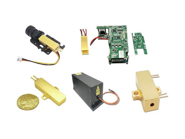

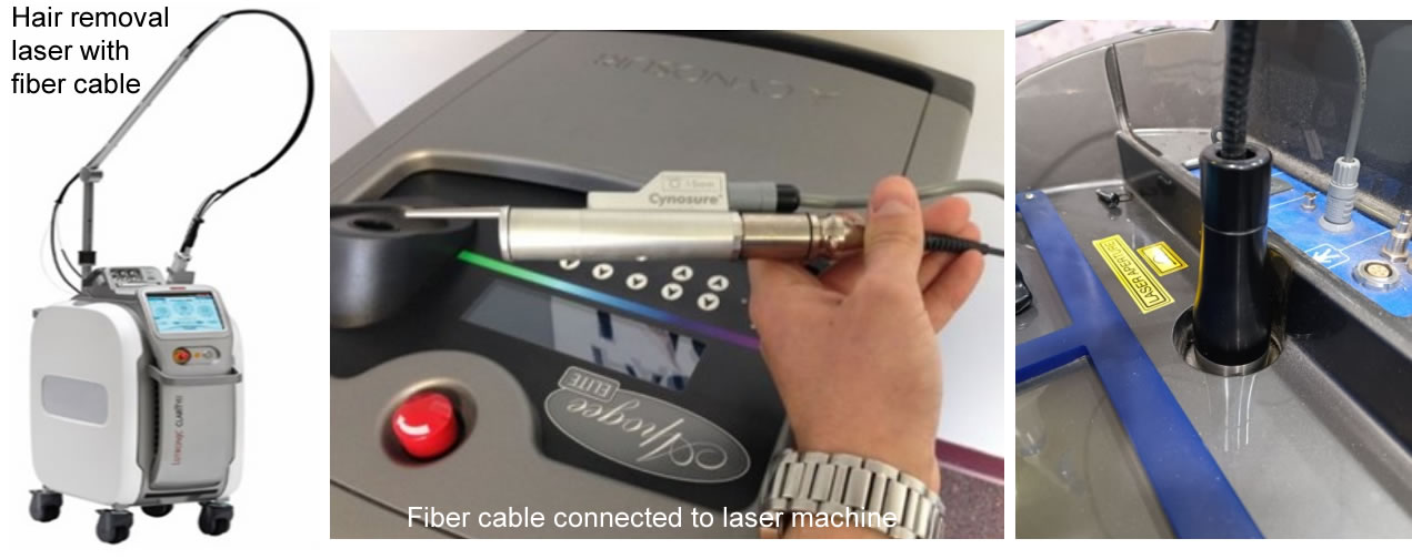
Recently, laser hair removal, a cosmetic procedure that uses lasers with radiation in the near infrared range (700 - 1063nm), has gained great popularity. The radiation of this range of light is well absorbed by melanin, which results in hair follicle destruction without subsequent restoration.
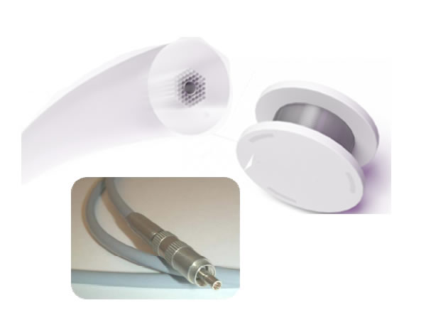
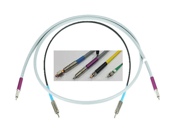
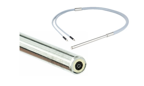
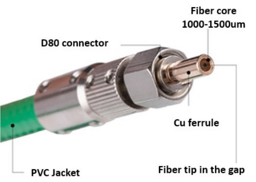
Today, there are many different types of hair removal lasers in the market. Despite their differences they all share one common feature, fiber optic cable. All hair removal lasers use fiber optic cable to transport the powerful laser beam to the target.
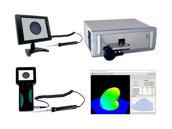
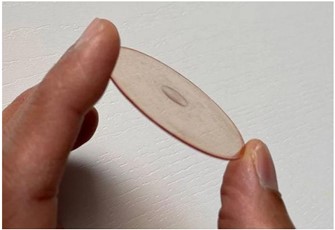
Fiber cables for hair removal, require large core diameter fibers to guide the light from the laser source to the tissue, from 1000 μm to 2000 μm, and high-quality fiber tip polishing is critical for the application. Failure can result in fiber burnt and malfunction of the laser application.
Fiber Cables for Hair Removal (specification)
| Cable type | STNIR1000-D80 | STNIR1200-D80 | STNIR1500-D80 |
| Fiber specifications | Core: 1000um ± 2% primary coating: 1100um ± 2% secondary coating: 1180um ± 3% protective coating: 1400um ± 5% |
core: 1200um ± 2% primary coating: 1320um ± 2% secondary coating: 1400um ± 3% protective coating: 1600um ± 5% |
core: 1500um ± 2% primary coating: 1650um ± 2% secondary coating: 1840um ± 3% protective coating: 2000um ± 5% |
| Numerical aperture (NA) | 0.22±0.02 | 0.22±0.02 | 0.22±0.02 |
| Spectral range | 0.4 – 2.4um | 0.4 – 2.4um | 0.4 – 2.4um |
| Connectors | D80 | D80 | D80 |
| Ferrule material | Cu | Cu | Cu |
| Fiber centratton in the ferrule | <10um | <10um | <10um |
| Cable length | Up to 5m | Up to 5m | Up to 5m |
| Protective tubing | PVC metal coated | PVC metal coated | PVC metal coated |
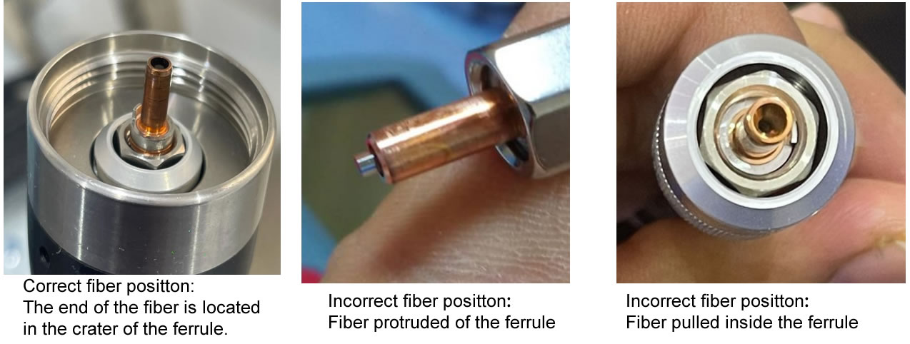
There are two very critical elements in the design of a fiber cable for hair removal laser, centricity of the fiber at the connector ends and fixation of the fiber at the connectors. Uncentered fiber may result in fiber tip damage, burnt, and can also harm the operator or patience. Inadequate fixation of the fiber at the connectors can lead to fiber protrusion or pull inside the connector. As a result, the laser focusing disrupts and the cable fails to perform.
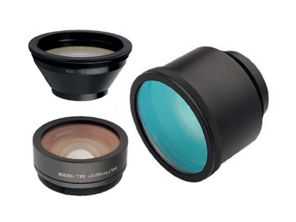
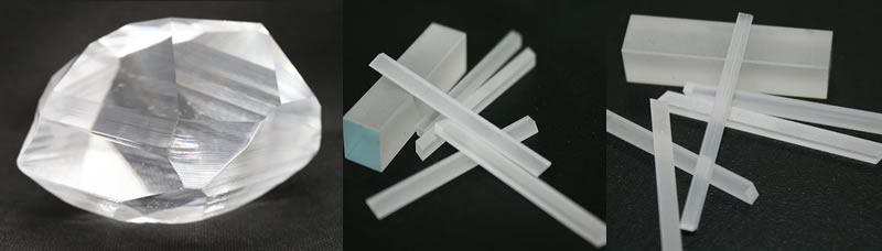
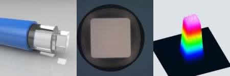
Square core fibers excel in specific applications where traditional circular core fibers with Gaussian outputs are not ideal. The uniform “top hat” intensity profile these fibers provide are the desired output profile when performing tasks such as welding, photolithography, and spectroscopy. Square core fibers with round claddings are also excellent candidates for use in the laser diode industry, where the square shape enables a more ideal coupling match with the diode source. We offer pure silica square core fibers with a fluorine doped cladding (0.22 NA) in a wide range of core diameters from 100 μm to 1000 μm.
Applications
Features
| Numerical Aperture | 0.22 ±0.02 |
| Core Sizes (Flat to Flat) | 100 μm to 1000 μm |
| Typical Clad/Core Ratio (RD clad ) | 1.2 (diagonal to Clad OD) |
| Dimensional Tolerances -Core/ Clad/ Jacket -Corner Rounding in Core (R/L) |
±2%/ ±2%/ ±5% ≤ 25% |
| Jacketing Options & Temp Range: -Acrylate -Nylon -Polyimide |
-40°C to +85 °C -40°C to +100 °C -190°C to +350°C |
| Proof Test Level (4 axis bend) -Acrylate/ Nylon -Polyimide |
100 kpsi 50 kpsi |
| Anti-Reflective Coating Option | Standard thin film coatings or RARe Motheye Nanosurfacing available upon request |
| Fiber Series | Core | Clad | OH Content |
| STASQR | Square | Round | Low |
| STSSQR | Square | Round | High |
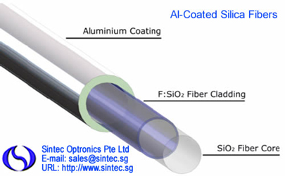
Aluminum coated silica fibers are the optimal solution for applications in high temperature, vacuum and harsh environment conditions.
Al-coated fibers have all benefits of silica-silica fibers. Additional significant advantages include a superior mechanical strength and better fatigue resistance compared to polymer coated fibers.
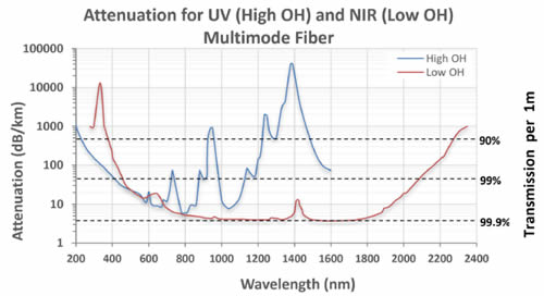
The transmission range spans 220 to 2400nm depending on UV or NIR silica fiber core choice. The working temperature range is from -270°C to 400°C; humidity – up to 100%.
| Code | Type | Core, μm | Cladding, μm | Coating Cu, μm | NA |
| ST100/110 Al | Step Index Multimode | 100 ± 2% | 110 ± 2% | 145 ± 5% | 0.22 |
| ST200/220 Al | Step Index Multimode | 200 ± 2% | 220 ± 2% | 270 ± 5% | 0.22 |
| ST400/440 Al | Step Index Multimode | 400 ± 2% | 440 ± 2% | 535 ± 5% | 0.22 |
| ST600/660 Al | Step Index Multimode | 600 ± 2% | 660 ± 2% | 745 ± 5% | 0.22 |
| ST50/125 Al | Graded Index Multimode | 50 ± 2% | 125 ± 2% | 165 ± 2% | 0.22 |
| ST9/125 Al | Graded Index Multimode | 9 ± 5% | 125 ± 5% | 165 ± 2% | 0.13 |
| Core/ Cladding material Step Index | Pure Fused Silica Core / Fluorine Doped Silica Cladding |
| Graded Index | Germanium Doped Fused Silica Core / Pure Fused Silica |
| Fiber core diameters, μm | 9; 50; 62.5; 100; 200; 400; 600 |
| Al coating thickness, μm | 15 – 150 (depending on fiber diameter) |
| Standard Numerical Aperture (NA) | 0.22 ± 0.02 |
| Available Numerical Aperture (NA) | 0.12 ± 0.02 / 0.26 ± 0.02 |
| Min operating temperature, °C | -270 |
| Max operating temperature, °C | +400 |
| Humidity Range | Up to 100% |
| Minimal bending radius (long term) | 200 x fiber outer diameter |
| Minimal bending radius (short term) | 100 x fiber outer diameter |
| Tensile strength (short gauge), GPa | 3.5 – 6 |
| Two point bending strength, GPa | >10 |
| Static fatigue parameter | >100 |
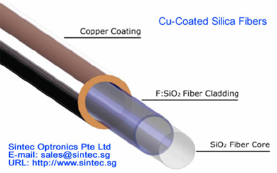
Our copper-alloy coated silica fibers are the optimal solution for applications in high temperature, vacuum and harsh environment conditions.
Cu-alloy coated fibers have all benefits of silica-silica fibers. Additional significant advantages include a superior mechanical strength and better fatigue resistance compared to polymer coated fibers.
The transmission range spans 220 to 2400nm depending on UV or NIR silica fiber core choice. The working temperature range is from -270°C to 600°C; humidity – up to 100%.
| Core/ Cladding material Step Index | Pure Fused Silica Core / Fluorine Doped Silica Cladding |
| Graded Index | Germanium Doped Fused Silica Core / Pure Fused Silica |
| Fiber core diameters, μm | 9; 50; 62.5; 100; 200; 400; 600 |
| Cu-alloy coating thickness, μm | 15 – 50 (depending on fiber diameter) |
| Standard Numerical Aperture (NA) | 0.22 ± 0.02 |
| Available Numerical Aperture (NA) | 0.12 ± 0.02 / 0.26 ± 0.02 |
| Min operating temperature, °C | -270 |
| Max operating temperature, °C | +600 |
| Humidity Range | Up to 100% |
| Minimal bending radius (long term) | 200 x fiber outer diameter |
| Minimal bending radius (short term) | 100 x fiber outer diameter |
| Tensile strength (short gauge), GPa | 3.5 – 6 |
| Two point bending strength, GPa | >10 |
| Static fatigue parameter | >100 |
| Code | Type | Core, μm | Cladding, μm | Coating Cu, μm | NA |
| 100/110 Cu | Step Index Multimode | 100 ± 2% | 110 ± 2% | 145 ± 5% | 0.22 |
| 200/220 Cu | Step Index Multimode | 200 ± 2% | 220 ± 2% | 270 ± 5% | 0.22 |
| 400/440 Cu | Step Index Multimode | 400 ± 2% | 440 ± 2% | 535 ± 5% | 0.22 |
| 600/660 Cu | Step Index Multimode | 600 ± 2% | 660 ± 2% | 745 ± 5% | 0.22 |
| 50/125 Cu | Graded Index Multimode | 50 ± 2% | 125 ± 2% | 165 ± 2% | 0.22 |
| 9/125 Cu | Graded Index Multimode | 9 ± 5% | 235 ± 5% | 165 ± 2% | 0.13 |
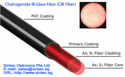
Chalcogenide As-S glass fiber transmits IR-radiation in the spectral range of 1.1–6.5μm. High performance CIR core/clad fiber are drawn with core diameters span from 8µm to 500µm.
Advanced drawing process with double polymer jacket provides a superior mechanical strength and high flexibility of CIR- fibers.
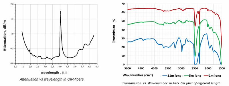
Low optical losses and small absorption peaks over the mentioned spectral range ensure a successful use of CIR-fiber for a wide range of applications.
| Transmission Range | 1.5 - 6μm |
| Core/Clad Structure | As2S3/As-S |
| Core/Clad Diameter | 200-500/300-600μm |
| Core Refractive Index | 2.4 |
| Effective NA | 0.28 |
| Protective Coating | Double Polymer Jacket |
| Ambient Temperature Range | 270 - 370 K |
Chalcogenide Infra Red (CIR) (1.5 - 6μm) fiber is drawn in core/clad structure with double polymer coating and characterized by a low optical losses and high flexibility. Delivery is from stock or within few weeks ARO. All standard cables include PEEK-polymer protective jacket and SMA termination.
| Part Number | STCIR8/300 | STCIR 50/250 | STCIR 250/300 | STCIR 340/400 | STCIR 500/550 |
| Type | Step Index Single-mode | Step Index Few-mode | Step Index Multimode | Step Index Multimode | Step Index Multimode |
| Core Dia., µm | 8±1 | 50±3 | 250±10 | 340±10 | 500±10 |
| Cladding Dia., µm | 300±15 | 250±10 | 300±15 | 400±15 | 550±15 |
| Protective Jacket Dia., µm | 400±20 | 410 ± 20 | 400 ±30 | 510 ± 30 | 700 ± 30 |
| NA | 0.25 ± 0.02 | 0.13 ± 0.02 | 0.30 ± 0.03 | 0.30 ± 0.03 | 0.30 ± 0.03 |
| Min Bending Radius,mm | 60 | 50 | 60 | 80 | 100 |
| Core/cladding composition | As2S3 |
| Spectral Range | 1.1 – 6.5μm |
| Core Refractive Index | 2.42 |
| Fresnel Reflection Losses | 31% |
| Attenuation at 3 – 4μm & 4.5µm – 5µm | 0.2 – 0.4dB/m |
| Effective Numerical Aperture NA | see Parameters of standard Chalcogenide fibers |
| Glass Transition Temperature, Tg | 185 °C |
| Operating Temperature | –273°C to +90°C |
| Core/Clad Diameter (standard) | see Parameters of standard Chalcogenide fibers |
| Protective Jacket | Fluoro polymer + PVC |
| Tensile Strength | >70 MPa |
| Minimum Bending Radius (fixed) | 100x [Fiber Diameter] |
| Minimum Elastic Bending Radius | 200x [Fiber Diameter] |
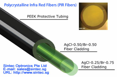
The development of specialty fibers for the Mid-Infrared region has resulted in a unique product - Core /
Clad Polycrystalline Infra-Red (PIR-) fibers. The PIR-fibers are non-toxic, very flexible, transparent across a broad spectral region 4 -18μm and capable of operating over the wide temperature range of 4K up to 420K. They are manufactured in a core/clad structure of superior quality from pure AgCl: AgBr solid solution crystals using an innovative vacuum extrusion method. They possess by no aging effect compared to an alternative bare core fiber. The range of PIR-fiber cables are available with a durable PEEK polymer jacket and terminations using either an SMA - type connector with a Ti or polymer ferrule or special one, manufactured on customer request. A wide variety of different optical coupling units can also be designed & fabricated for specialized customer requirements.
| Part Number | STPIR240/300 | STPIR400/500 | STPIR600/700 | STPIR900/1000 |
| Type | Step Index Multimode | Step Index Multimode | Step Index Multimode | Step Index Multimode |
| Core Dia., µm | 240±10 | 400±10 | 600±10 | 860±20 |
| Cladding Dia., µm | 300+0/-10 | 500+0/-15 | 700+0/-15 | 1000+0/-20 |
| Protective Jacket Dia., µm | no | no | no | no |
| NA | 0.35±0.05 | 0.35±0.05 | 0.35±0.05 | 0.35±0.05 |
| Min. bending Radius, mm | 45 | 75 | 100 | 150 |
| Core/cladding composition | AgCl:AgBr |
| Spectral Range | 3 – 18μm |
| Core Refractive Index | 2.15 |
| Fresnel Reflection Losses | 25% |
| Attenuation at 10.6 µm | 0.2 – 0.4dB/m |
| Effective Numerical Aperture NA | 0.35 +/- 0.05 |
| Melting Point | 410 °C |
| Operating Temperature | –273 to +140°C |
| Core/Clad Diameter (standard) | see Parameters of standard Polycrystalline fibers |
| Laser Damage Threshold for CW CO2 laser | >12kW/cm² |
| Tensile Strength | > 70MPa |
| Minimum Bending Radius (fixed) | 5 x [Fiber Diameter] |
| Minimum Elastic Bending Radius | 150 x [Fiber Diameter] |
PIR-fibers are protected by a loose PEEK-jacket (PolyEtherEtherKetone) to provide stiff, flexible and hermetic protection against mechanical, photoinduced and chemical damage over a wide temperature range up to 250°C.
Diverse Methods of AR-coating and SMART-treatment
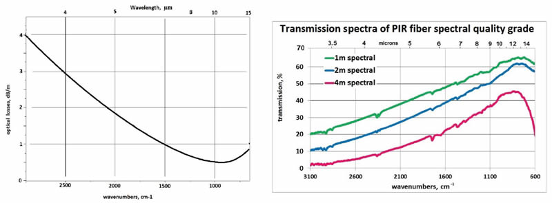
Comparison of Standard and Spectral PIR-fibers
Typical transmission spectra of 1.5m long PIR-900/1000 fiber (red) versus CIR-750/850 fiber (blue) (includes reflection & coupling losses at fiber ends without AR coating and some absorption bands of atmospheric moisture, etc.)
Typical specification of CIR- and PIR-fibers
| No. | Parameter | CIR-Fiber | PIR-Fiber |
|---|---|---|---|
| 1 | Transmission range | 1.5 to 6μm or 1600- 6500cm-1 | 3 to 18μm or 550 - 3300cm-1 |
| 2. | Core/Clad structure materials | Chalcogenide As-S glasses | AgCl:AgBr solid solution crystals |
| 3. | Specific Features | Toxic & Fragile, Non-hygroscopic | Non-toxic, Non-hygroscopic, very flexible, slightly UV-sensitive |
| 4. | Core/Clad diameter | 200-500/300-600μm | 400/500, 630/700, 700x700, 900/1000μm |
| 5. | Core refractive index | 2,4 | 2,2 |
| 6. | Effective NA | 0,28 | 0,25 |
| 7. | Optical losses | Minimum of 0,2dB/m at wavelengths 2-4μm | Minimum of 0,2-0,3dB/m at wavelengths 10-12μm |
| 8. | Operation temperature | From 270 to 370K | From 4 to 420K |
| 9. | Max length of cable | Up to 50-100 meters | Up to 20-40 meters |
Comparison of PIR- and CIR-Fibers Transmission Spectra for 1.5m length
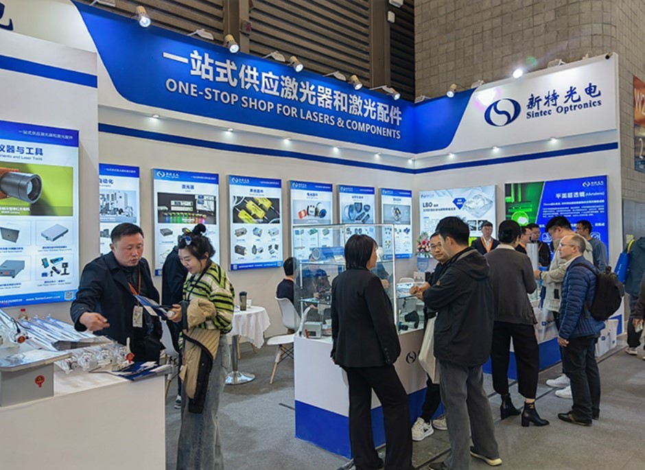
A leading supplier and manufacturer of a wide range of photonics products such as lasers,laser parts & machines.
Office: 10 Bukit Batok Crescent #07-02 The Spire Singapore 658079
Tel: +65 63167112
Fax: +65 63167113
Whatsapp: +65 91904616