 English
 Français
 Deutsch
 euskara
 Русский язык
 Italiano
 Português
 Nederlands
 Polski
 Greek
Greek Lietuva
 Türkçe
 日本語
日本語 한어
한어 中文
中文 தாமில்
 فارسی
فارسی हिंदी
हिंदी Tiếng Việt
 ภาษาไทย
 Pilipino
 Indonesia
 தாமில்
Send us a message
CLOSE


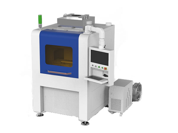


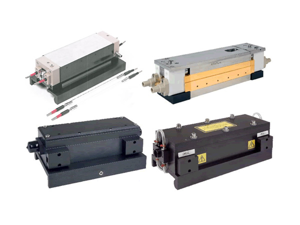
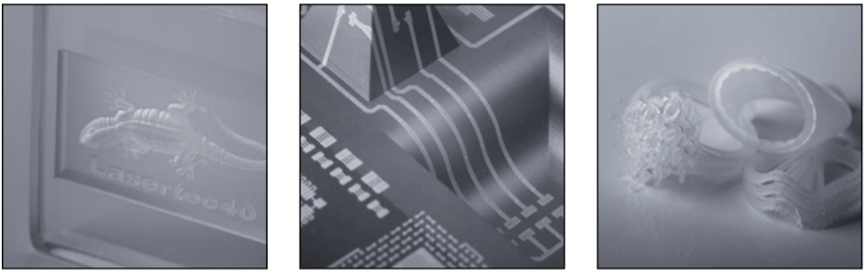
Pre-focusing deflection units are developed due to cost and size limitations on the output lens and the beam aperture limitations with 2-axis deflection units, which limit their ability to produce smaller spot sizes over medium size scanning fields. Pre-focusing deflection units meet customers application requirements for large processing fields with smaller spot sizes and allow the user to change the working distance, field and spot size with the same deflection unit. 3-axis technology also benefits application-on-the-fly with moving targets, while in 3D-applications, the setup enables processing of non-flat parts or uneven surfaces and high power products. These solutions are now available for Nd:YAG, diode, and CO2-lasers.
In a pre-focusing deflection unit, the laser beam first enters a moving lens - the Linear-Translator-Module. A moving lens diverges the beam rapidly before it passes one or two focusing lenses. Then the beam hits a deflection unit that directs the laser towards any X-Y position inside the marking field.
In a deflection unit without focus correction, the focused laser spot at the centre of the field describes an arc when moved in either axis, creating a sphere of focused points above the working field. At locations away from the centre of the working field, the laser beam is not focused. This is due to the increased length from the lens to the workpiece, as the scanners direct the beam away from the centre of the field.
In a pre-focusing deflection unit, focus compensation is accomplished by slight adjustments in the distance between the moving lens and the focusing lens, as the scanners direct the beam across the working field by a third moving Z-axis, hence the name “pre-focusing deflection unit”.
Large, pre-adjustable processing field sizes from 250 x 250 mm² to 850 x 850 mm²
Dust-proof with additional protective window and optional monitoring
“High Power” version for welding in the e-mobility market or “High Dynamic” version for the powder-bed process (SLM) in additive manufacturing
Integrated fiber collimator and integrated process light output
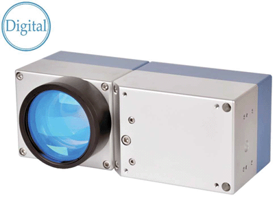
HIGHLY PRACTICAL, EASILY INTEGRATED
YOUR BENEFITS: The deflection system can be easily integrated into any laser system by means of various mechanical interfaces below, to the side (robot flange is possible) and from above. The integrated fiber collimator enables connection of the laser fiber without beam path alignment. A second external protective window can be quickly and easily replaced, with optional monitoring available. Camera and welding monitoring systems can be adapted to the process light output without aberrations. The AXIALSCAN FIBER-30 is completely dust-proof and is therefore ideal for use in a harsh industrial environment.
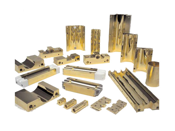
CONFIGURABLE THROUGH AND THROUGH: Suitable mirrors are available both for high-performance welding applications with laser power in the multi-kilowatt range and for highly dynamic applications. Optical configurations are available for all standard beam parameters of lasers and their fibers. We would also be happy to help you put together the perfect configuration for your application.
TYPICAL APPLICATIONS: The AXIALSCAN FIBER-30 is the result of our continuous and heavily market-oriented enhancement of the AXIALSCAN model range for fiber-coupled laser applications; ideal for welding in the e-mobility market with optional laser beam modulation or for powder-bed machines in additive manufacturing (SLM). Combined into a “quadruple design”, the productivity of one AM machine is boosted fourfold for each processing field. The integrated process light output enables the connection of application-appropriate process monitoring sensors, thereby allowing quality parameters to be guaranteed and documented.
INNOVATION AND QUALITY: Innovation and maintaining high product quality standards are our priorities at RAYLASE. All our products are developed, built and tested in our own laboratories and production facilities. Through our world-wide support network we can offer best maintenance and rapid service for our customer.
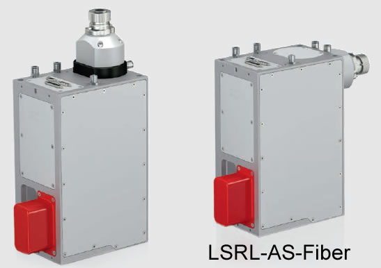
Specifications of LSRL-AS-FIBER-30
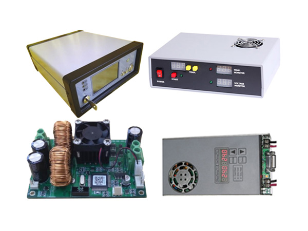
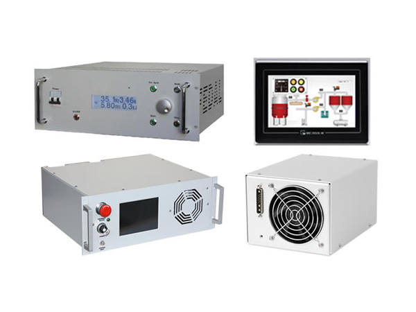
Power supply: Voltage: +48 V; Current: 4 A, RMS, max. 8 A; Ripple/Noise: Max. 200 mVpp@ 20 MHz bandwidth
Ambient temperature: +15°C to +35°C
Storage temperature: -10°C to +60°C
Humidity: ≤ 80 % non-condensing
IP Code: 64
Interface signals: Digital RL3-100 protocol 20 Bit and XY2-100 protocol 16 Bit or SL2-100 protocol 20 Bit
Wavelengths and substrates: 1060nm – 1080nm, QU; 1060nm – 1090nm + AL (QU = quartz; SC = silicon carbide)
Vector-Tuning (VC): Optimized tuning for a wide range of applications with emphasis on processing speed
Hatching Tuning (H): Optimized tuning for high precision beam deflection and fastest beam direction change during hatching
| Standard | HPS* | ||
| Typical deflection (optical) | ± 0.384 rad | ± 0.384 rad | |
| Resolution XY2-100-E 16-Bit | 12 μrad | 12 μrad | |
| Resolution RL3-100 / SL2-100 20-Bit | 0.76 μrad | 0.76 μrad | |
| Repeatability (RMS) | < 2.0 μrad | < 0.4 μrad | |
| Position noise (RMS) | < 3.2 μrad | < 2.0 μrad | |
| Temperature Drift | Max. Gaindrift ¹ | 15 ppm/K | 8 ppm/K |
| Max. Offsetdrift ¹ | 10 μrad/K | 15 μrad/K | |
| Long-term drift 8 h without water temperature control ¹ | < 60 μrad | < 50 μrad | |
| Long-term drift 8 h with water temperature control ¹, ² | < 40 μrad | < 30 μrad | |
Remark: 1. Angles optical. Drift per axis, after 30 min warm-up, at constant ambient temperature and process stress. 2. After 30 min warm-up, under varying process loads, with water temperature control set for ≥ 2 l/min and 22˚C water temperature. 3. HPS* is High Performance System.
| Deflection unit | LSRL-AS-FIBER-30 | |
| Laser fiber socket | QBH | |
| Position of fiber socket | optional above (T) or behind (R) | |
| Weight (kg) | approx. 12 | |
| Dimensions excluding fiber socket and electrical plug connections (L x W x H) (mm) | 270.0 x 140.0 x 320.0 | |
| Typ. beam divergence | max. beam divergence | |
| Optical sets for fiber coupling¹ | 1/e² full angle | 1/e² full angle |
| Single-mode laser, fiber core 10 μm or multi-mode laser BPP approx. 3.5 mm x mrad, fiber core 100 μm | 140 mrad | 150 mrad |
| Single-mode laser, fiber core 14 μm | 100 mrad | 110 mrad |
| Single-mode laser, fiber core 20 μm | 80 mrad | 90 mrad |
| Single-mode laser, fiber core 30 μm | 50 mrad | 64 mrad |
Remark: 1. Optical sets optimized for maximum beam divergence
| LSRL-AS-Fiber-30-QU | LSRL-AS-Fiber-30-SC | LSRL-AS-Fiber-30-SC-HPS | |
| Tuning | VC | H | H |
| Processing speed (rad/s) | 50 | 30 | 30 |
| Positioning speed (rad/s) ¹ | 50 | 30 | 30 |
| Tracking error deflection unit (ms) ² | 0.48 | 0.23 | 0.25 |
| Step response time at 1% of full scale (ms) ³ | 1.2 | 0.7 | 0.66 |
| Tracking error focusing unit (ms) | 1.5 | 1.5 | 1.5 |
| Speed of moving lens (mm/s) | 880 | 880 | 880 |
Remark: 1. See “Calculation of speed”. 2. Calculation acceleration time approx. 1.7 x tracking error. 3. Setting to 1/5,000 of full scale.
Calculation of maximum speed in field:
1 rad/s @ ± 0.384 rad deflection (44°)
0.13 m/s for 100 mm working field size.
Example: AXIALSCAN FIBER-30 QU, Working field size 400 mm × 400 mm (field factor = 4), Positioning speed 50 rad/s => 50 × 0.13 m/s × 4 = 26 m/s.
Note: Lower speeds may be produced by the linear translator module, depending on which control card is used, the laser job, field size and optical configuration.
Options:
AXIALSCAN FIBER-30 deflection units offer the option of water cooling (W) of the electronic components and galvanometer scanner along with air-cooling (A)
for the deflection mirrors (> 2 kW laser power for SC-mirrors and > 3 kW laser power for QU-mirrors).
This ensures constant working conditions and excellent long-term stability and guarantees reliable operation of high-power laser applications.
AXIALSCAN FIBER-30 deflection units can also be operated without water cooling. Without water cooling, drift values may increase.
Option of additional protective window:
Each AXIALSCAN FIBER can be equipped with an optional extra protective window. This external protective window is housed under a flap and is quickly replaced.
This ensures fast and easy replacement of the protective window under harsh conditions in dusty environments. This means that all cleaning of the protective window
is done externally and the system is operational again after a very short time.
An optional automatic monitoring of the level of contamination of the protective window is currently in development.
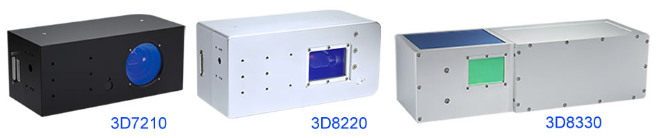
| Part number | Max entrance dia. mm | DC power supply, V | Dimension LxWxH,mm |
| LSJC-xxxx-3D7210 | 10 | 24 | |
| LSJC-xxxx-3D2207 | 12 | 24 | 262x110x110 |
| LSJC-xxxx-3D8220 | 20 | 24 | |
| LSJC-xxxx-3D8230 | 30 | 24 | 556.3x176x158 |
| LSJC-xxxx-3D8330 | 30 | 24 |
| Part Number | LSJC-1064-10-3D7210-300 | LSJC-355-10-3D7210-200 | LSJC-xxxx-12-3D2207 |
| Input Aperture | 10mm | 10mm | 12mm |
| Mark field | 300x300mm | 200x200mm | |
| Linearity | 99.9% | 99.9% | 99.9% |
| Small step response time | 0.3ms | 0.3ms | 0.45ms |
| Maximum Scan Angle | ±15° | ±15° | ±15° |
| Resolution | 12μrad | 12μrad | 12μrad |
| Repeatability | 8μrad | 8μrad | 8μrad |
| Working Temperature | 0-45℃ | 0-45℃ | 0-45℃ |
| Storage Temperature | -10 to +60℃ | -10 to +60℃ | -10 to +60℃ |
| Input Voltage | ±24VDC | ±24VDC | ±24VDC |
| Interface Signal Digital | XY2-100 | XY2-100 | XY2-100 |
| Dimension(L×W×H) | 262x110x110 |
| Part Number | LSJC-1064-20-3D8220-500 | LSJC-10.6-30-3D8230-300 | LSJC-10.6-30-3D8330-1200 |
| Input Aperture | 20mm | 30mm | 30mm |
| Mark field | 500x500mm | 300x300mm | 1200x1200mm |
| Linearity | 99.9% | 99.9% | 99.9% |
| Small step response time | 0.8ms | 1.2ms | 1.2ms |
| Maximum Scan Angle | ±15° | ±15° | ±15° |
| Resolution | 12μrad | 12μrad | 12μrad |
| Repeatability | 8μrad | 8μrad | 8μrad |
| Working Temperature | 0-45℃ | 0-45℃ | 0-45℃ |
| Storage Temperature | -10 to +60℃ | -10 to +60℃ | -10 to +60℃ |
| Input Voltage | ±24VDC | ±15VDC | ±15VDC |
| Interface Signal Digital | XY2-100 | XY2-100 | XY2-100 |
| Dimension(L×W×H) | 556.3x176x158 |
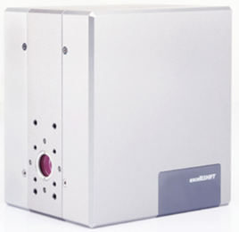
Our new excelliSHIFT extends a 2D scan head into a highly dynamic 3D system. Based on tried-and-proven galvanometer technology, its completely new design drastically improves dynamic performance compared to conventional z-axes. The Z-scanner is no longer a limiting factor, so that identical acceleration can be achieved in all in all three spatial directions. This opens up entirely new possibilities for laser processing of 3-dimensional, complexly-shaped surfaces. Moreover, the new technology uses no transmissive optical components. That means dispersion effects are avoided when working with different wavelengths, and thermal-lens effects are minimized, too.
Highest reliability due to field-proven galvanometer technology
High-dynamic processing of complex 3D-surfaces
Designed without transmissive optical components
Flat field correction of pre-focused systems without dynamic limitations
Position-independent mounting
Micromachining
Marking of curved surfaces
Deep engraving
Ultra-fast 3D processing
| Part number | LSSL-14-excelliSHIFT |
| Aperture | 14mm |
| Wavelength | 515nm – 532nm, 1030nm – 1070nm (1) |
| Beam expansion | 1-fold |
| Tracking error | 0.1ms |
| Beam guidance | Reflective |
| Dimensions WxHxD | (115x160x142)mm3 |
| Weight | 3.7kg |
| Laser power (with cooling) | 120W, green; 200W, IR |
| Focus range (2) | ±14mm |
| Focus speed in image field (2) | Up to 30m/s |
(1) Other wavelengths availabe on request
(2) With f-theta lens f = 160mm; at large focal lengths, corresponding higher values are achieved
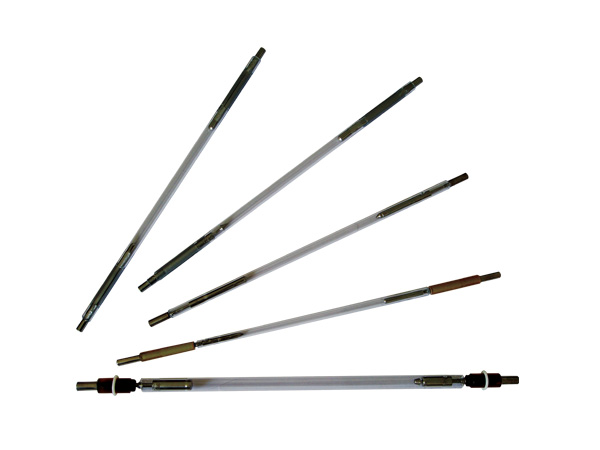
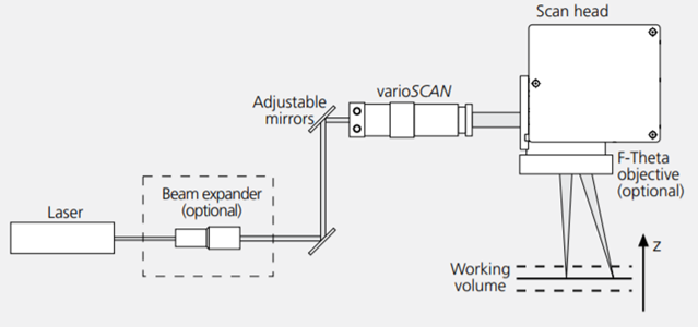
We also offer Z-Scanner modules. The varioSCAN can extend XY scan systems into 3D beam deflection systems. The laser focus is guided along the contour of the workpiece being processed, thus enabling processing in three dimensions.
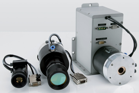
During the scanning process, a perging optic in the varioSCAN is positioned with high dynamics along the optical axis with respect to a stationary focusing optic. This produces a change in the system’s overall focal length, synchronized with the mirror motion. The varioSCAN focusing unitcan thereby expand 2D scan systems into 3-axis scan systems.
| varioScan 20 | varioScan 40 | |
| Beam input aperture | Up to 8mm | Up to 16mm |
| Output aperture | Up to 20mm | Up to 40mm |
| Motor – maximum lens travel | ±1mm | ±1.5mm |
| Motor – tracking error | 0.9ms | 1.4ms |
| Motor – typical travel speed | ≤140mm/s | ≤100mm/s |
| Motor – repeatability | <1µm | <1µm |
| Motor – nonlinearity | 1.5% FS | 1.5% FS |
| Motor – long-term drift (over 8 hours, at constant environmental conditions) | <6µm | <10µm |
| Power requirements | ±(15+1.5)V DC, max. 1.5A each | ±(15+1.5)V DC, max. 1.5A each |
| Part number | Max entrance dia. mm | Control | DC power supply, V | Dimension LxWxH,mm |
| LSRM-1064-6-QPT | 6 | XY2-100 | 15 | 254x97x105 |
| LSRM-1064-7.2-QPT | 7.2 | XY2-100 | 15 | 254x97x105 |
| LSRM-1064-8.4-QPT | 8.4 | XY2-100 | 15 | 254x97x105 |
| LSRM-532-3.3-QPT | 3.3 | XY2-100 | 15 | 274x109x116 |
| LSRM-532-4-QPT | 4 | XY2-100 | 15 | 274x109x116 |
| LSRM-532-4.6-QPT | 4.6 | XY2-100 | 15 | 274x109x116 |
| LSRM-xxxx-QP20 | XY2-100 | 15 | 350x140x188 | |
| LSRM-xxxx-QP30 | XY2-100 | 15 | 400x155x194 |
(Refer to LSRM-Q datasheets for 2D marking heads)
This solution includes a 2D galvoscanner system LSRM-Q Series, a dynamic focusing unit Proton Series, F-theta lens and a galvo system controller LSRM-UMC4. It uses the post-objective scanning technology, the working volume is about 150*150*45 with the FL 210mm F-theta lens. The advantages are fast marking speed, small focal spot and low power loss.
| Laser type | Nd:YAG | Nd:YAG doubled |
| Wavelength | 1064nm | 532nm |
| Beam expansion factor | 1.67 | 3 |
| Input aperture | 6mm/7.2mm/8.4mm | 3.3mm/4mm/4.6mm |
| Scan head apertures | 10/12/14mm | 10/12/14mm |
| Focus range in Z-direction | ±22.5mm (1) | ±2.5mm (2) |
| Tracking error time | 700us | 700us |
| Dimension | 254x97x105mm | 274x109x116mm |
| Remarkds: (1) The focal length of the f-theta lens is 210mm; (2) The focal length of the f-theta lens is 100mm. All the above parameters are theoretical. | ||
(Refer to LSRM-Q10/12/14 datasheet for 2D marking heads)
LSRM-QP20/30: 3D Pre-Scanning Solution includes a 2D galvoscanner system LSRM-Q, a dynamic focus unit Proton series, and a galvo system controller LSRM-UMC4. It uses the Pre-Objective Scanning technology to realize the large field and 3D laser application. The advantage of this system: fast, small focal spot, small power loss.
| Scanning field | 600x600mm | 800x800mm |
| Focal spot diameter | 364um | 487um |
| Working distance | 502mm | 777mm |
| Resolution | 9um | 12um |
| Scanning field | 400x400mm | 600x600mm | 800x800mm |
| Focal spot diameter | |||
| QP-20 | 34um | 52um | — |
| QP-30 | - | 36um | 48um |
| Working distance | |||
| QP-20 | 502mm | 777mm | — |
| QP-30 | - | 777mm | 1051mm |
| Resolution | 6um | 9um | 12um |
| Scanning field | 400x400mm | 600x600mm |
| Focal spot diameter | 17um | 26um |
| Working distance | 520mm | 795mm |
| Resolution | 6um | 9um |
All of the above parameters are theoretical values.
Distance between edge of deflection unit and working surface. This distance is dependent on the product model and will vary with laser pergence and objective tolerance.
Actual spot size and writing speed are dependent on material and application.
A leading supplier and manufacturer of a wide range of photonics products such as lasers,laser parts & machines.
Office: 10 Bukit Batok Crescent #07-02 The Spire Singapore 658079
Tel: +65 63167112
Fax: +65 63167113
Whatsapp: +65 91904616