 English
 Français
 Deutsch
 euskara
 Русский язык
 Italiano
 Português
 Nederlands
 Polski
 Greek
Greek Lietuva
 Türkçe
 日本語
日本語 한어
한어 中文
中文 தாமில்
 فارسی
فارسی हिंदी
हिंदी Tiếng Việt
 ภาษาไทย
 Pilipino
 Indonesia
 தாமில்

Send us a message
CLOSE


")
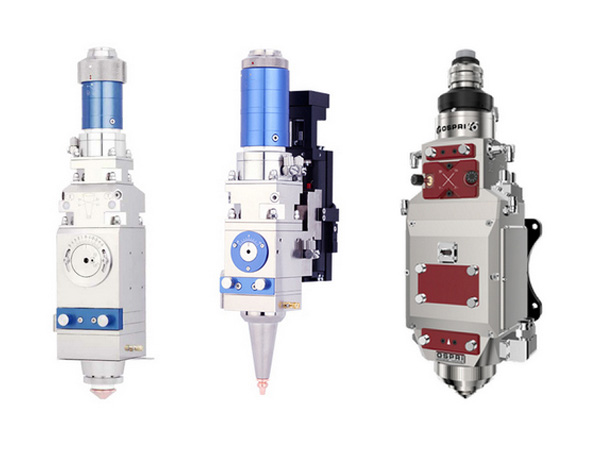
Our LSSL-BC series scan heads are the ideal entry-level 2D scan systems for deflecting and positioning laser beams in the working plane. The basiCube scan head series offers superior cost effectiveness and is optimized for coding and marking.
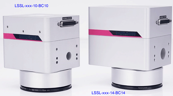
Features:
Compact & light-weight design
Very fast writing speed
Excellent price/performance ratio
Specifications:
| Model | LSSL-xxxx-10-BC10 | LSSL-xxxx-14-BC14 | |
| Aperture (mm) | 10 | 14 | |
| Tracking error (ms) | 0.14 | 0.18 | |
| Marking speed(1) (m/s) | 2.5 | 2.0 | |
| Positioning speed (m/s) | 12.0 | 12.8 | |
| Step response time(2) - 1% of full scale (ms) | 0.35 | 0.45 | |
| Step response time - 10% of full scale (ms) | 1.0 | 1.4 | |
| Typical scan angle (rad) | ±0.35 | ||
| Gain error (mrad) | <5 | ||
| Zero offset (mrad) | <5 | ||
| Power supply | ±15 V DC, max. 3 A each | 24 V / 30 V DC, max. 3 A each | |
| Interface (digital) | SL2-100, XY2-100 | ||
| IP protection class | IP 50 | ||
| Operating temperature(°C) | 25 ± 10 | ||
| Repeatability – RMS (μrad) | <2.0 | ||
| Positioning resolution(3) (bit) | 16 | ||
| Nonlinerity | < 3.5 mrad / 44° | ||
| Temperature drift – offset (μrad/K) | <30 | ||
| Temperature drift – gain (ppm/K) | <160 | ||
| 8h drift – offset (μrad) | <100 | ||
| 8h drift – gain (ppm) | <250 | ||
| Beam displacement (mm) | 12.54 | 16.42 | |
| Dimension (mm) | 106x91x91 | 123x95x104 | |
| Weight (kg) | 1.5 | 2.15 | |
(1) With F-theta lens, f = 160mm;
(2) Setting to 1/1000 of full scale;
(3) Based on the full angle range (e.g. positioning resolution 11 μrad for angle range ±0.36 rad)
Options:
Coatings for the following wavelengths: LSSL-BC10: 355nm, 532nm, 1064nm and 10600nm; LSSL-BC14: 1064nm and 10600nm.
Suitable objectives available for various image fields and focal lengths.
Extension into a 3-axis scan system.
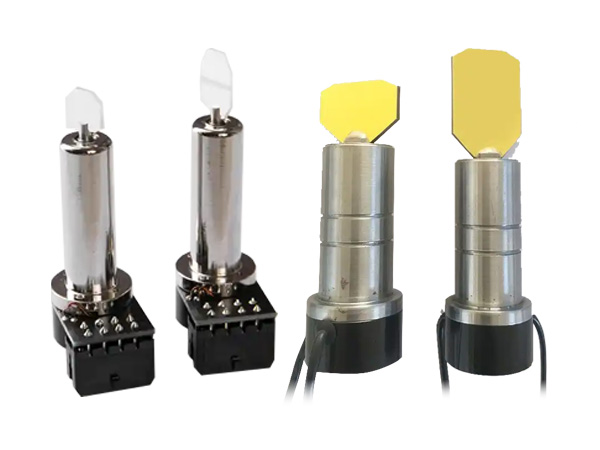
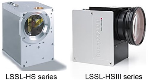
LSSL SC series laser marking head is an ultra-compact one which delivers excellent dynamics and superior product quality in a minimum-size package. The solid performance of the marking heads is made possible by the new, miniaturized servo amplifiers and industry-proven OSSL series galvanometer optical scanners. Aperture of 7, 10 and 14mm are available.
Sealed against water and dust, the LSSL robust and exceptionally compact housing facilitates straightforward integration into production environments-even confined, difficult to-access locations. A wide variety of objectives can be used with these scan heads.
Versions with analog or digital interfaces are available. The digital version can be simply controlled via a PCI interface board or PC-independent standalone board. LSSL scan heads are ideally suited for solutions requiring very high marking speeds and integration in confined spaces. Applications include coding in the packaging industry or the marking of electronic components – areas traditionally served by inkjet systems.
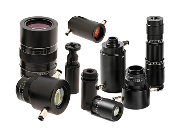
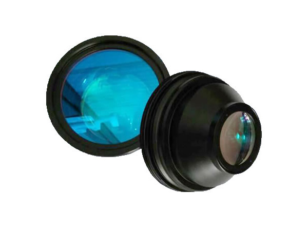
Optics
We precisely optimize and tune all optical components to one another to ensure maximum focus quality and stable process parameters. Optical components offered by us include exceptionally compact objectives, as well as objective adapters for standard objectives. Optics for various wavelengths, power densities, focal lengths and image fields are available.
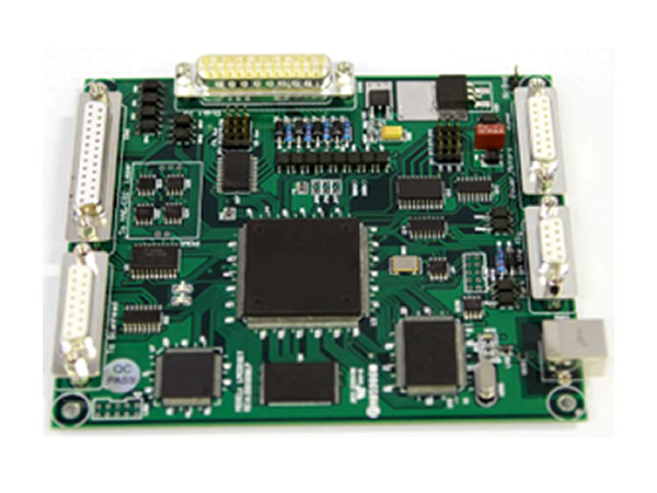
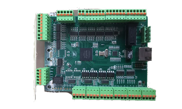
Control
LSSL marking heads are equipped with either an analog or a digital standard interface accessible via a 25-pin D-SUB connector. They are easily controlled via PC interface board or the PC-independent standalone board from us.
Quality
The high quality is the result of years of experience in the development and manufacture of galvanometer optical scanners and scan systems. In addition, every scan system must first pass the quality check burn-in test before it is released for shipment to the customer.
Common Specifications (all angles are in optical degrees)
| Dynamic Performance | Repeatability | < 22μrad |
|---|---|---|
| Offset drift | 30μrad/K | |
| Gain drift | 80ppm/K | |
| Long-term drift over 8 hours | < 0.3mrad, plus temperature induced gain and offset drift | |
| Optical Performance | Typical scan angle | ±0.35rad |
| Gain error | < 5mrad | |
| Zero offset | < 5mrad | |
| Nonlinearity | < 3.5mrad | |
| Interface | Analog version | ±4.8 V |
| Digital version | XY2-100 standard | |
| Operating Temperature | 25 °C ± 10 °C |
Product-Dependent Specifications (all angles are in optical degrees)
| Part number | LSSL-xxx-7-XS | LSSL-xxx-10-S | LSSL-xxx-14-M |
|---|---|---|---|
| Aperture | 7mm | 10mm | 14mm |
| Beam displacement | 9.98mm | 12.54mm | 16.42mm |
| Dynamic Performance Tracking error | 0.14ms | 0.18ms | 0.30ms |
| Step Response Time (settling to 1/1000 of full scale) 1% of full scale 10% of full scale | 0.30ms 0.70ms | 0.40ms 1.2ms | 0.65ms 1.6ms |
| Typical speeds Marking speed Positioning speed Writing speed with good writing quality Writing speed with high writing quality | 2.5m/s 12.0m/s 900cps 600cps | 2.0m/s 7.0m/s 640cps 400cps | 1.0m/s 7.0m/s 410cps 280cps |
| Power Requirements | ±15VDC max. 2A each | ±15VDC max. 3A each | ±15VDC max. 3A each |
| Dimension | 79x69x78mm | 114x97x94mm | 134x100x106mm |
| Weight (without objective) | 650g | 1.9kg | 2.3kg |
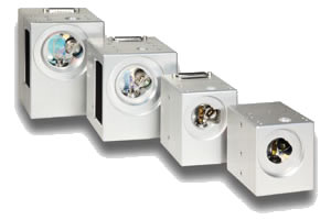
These compact scan heads provide optimal solutions for nearly all challenges found in industrial laser materials processing. The mechanically and electrically inter-compatible scan heads have apertures ranging from 7 to 30 mm and various levels of dynamics. High long-term stability and low drift values are ensured via integrated temperature stabilization.
We have products for practically every customer needs. Small aperture systems optimally combine top speed and exceptional precision. Marking speeds exceeding 1000 characters per second can be achieved.
Also available are large-aperture scan heads offering small spot size, high speed and laser-power handling up to the multi-kilowatt range.
The housing concept as well as tight manufacturing and assembly tolerances bring high flexibility and certainty to the design and operation of laser materials processing systems. This also facilitates speedy adaptation to inpidual customer requirements. In conjunction with new electronics, these scanners deliver highest dynamic performance, lowest drift and best linearity.
Materials processing
Marking
Micro-structuring
Rapid manufacturing
3D applications
Processing-on-the-fly
Scan mirrors and objectives with optimized mounts are available for all typical laser types and working fields. To optimally utilize standard objectives, LSSL-HS-25’s two scan axes have differing maximum scan angles. This results in an elliptical image field with the larger semi-axis perpendicular to the entrance beam axis.
All scan heads of these series are equipped with either analog or digital standard interfaces and are easily controlled via our control boards. All scan heads are optionally available with an optical fiber data interface.
Threaded and non-threaded holes at the housing’s beam entrance side of LSSL-HS-20, -25 and -30 facilitate mounting of the scan head and installation of fiber optic outputs. On the beam exit side, threaded holes are available for attaching add-on components such as cross jets, illumination, distance sensors or thermal shields.
The LSSL-HS-20, -25 and -30 scan heads provide water-cooling connections for the entrance aperture, electronics and galvanometer scanners, along with air-cooling of the deflection mirrors. This ensures constant working conditions and excellent long-term stability, thus guaranteeing reliable operation even in high-laser-power applications.
Upgrade to a 3-axis scan system
High-performance variants with lightweight mirrors (14 mm apertures and higher)
Available as a scan module without housing (except LSSL-HS-30)
Water and air cooling (10 mm apertures and higher; standard for LSSL-HS-20, -25 and -30)
Camera adapter for optical process monitoring
| Repeatability (RMS) | < 2 μrad |
| Positioning resolution | 18 bit (8) |
| Optical performance Gain error Zero offset Skew | < 5 mrad < 5 mrad < 1,5 mrad |
| Power requirements | ±(15+1.5) V DC, max. 3 A (max. 6 A for LSSL-HS-20-30) |
| Input signals Digital version Analog version | SL2-100, XY2-100 Standard or optical data transfer alternatively: ±4.8 V; ±9.6 V; ±4.8 mA; ±9.6 mA |
| Output signals Digital version Analog version | 3 status signals per axis S L2-100, XY2-100 Standard or optical data transfer TTL level |
| Operating temperature | 25 °C ± 10 °C |
| Typical air requirements (9) | clean, filtered air 20 l/min at Δp < 2 bar |
| Typical water requirements | 5 l/min at Δp < 0.1 bar, p < 4 bar |
| (all angles are in optical degrees) (8) based on the full angle range (e.g. positioning resolution 2.8 μrad for angle range ±0.36 rad), resolutions better than 16 bit (11 μrad) only together with SL2-100 interface (9) air and water cooling optional for LSSL-HSIII-10 & 14 and LSSL-HS10 | |
| Part number | LSSL-HS10 | LSSL-HS20 | LSSL-HS25 | LSSL-HS30 |
| Aperture | 10 mm | 20 mm | 25 mm | 30 mm |
| Tracking error | 0.18 ms | 0.35 ms | 0.50 ms | 0.55 ms |
| Step response time(1) 1% of full scale 10% of full scale | 0.35 ms 0.90 ms | 0.80 ms 2.50 ms | 0.90 ms 3 .20 ms | 1.20 ms 4.50 ms |
| Typical speeds(2) Marking speed Positioning speed Writing speed Good writing quality High writing quality | 2.0 m/s 7.0 m/s 640 cps 400 cps | 1.0 m/s 6.0 m/s 320 cps 210 cps | 0.8 m/s 5.0 m/s 260 cps 170 cps | 0.7 m/s 3.0 m/s 220 cps 150 cps |
| Long-term drift | < 0.6 mrad(7) | < 0.6 mrad(7) | < 0.6 mrad(7) | < 0.6 mrad(7) |
| Optical performance Typical scan angle of scanner 1 Typical scan angle of scanner 2 Typical field size – ellipse (2), (4) Typical field size – square (2), (4) Nonlinearity | ±0.35 rad ±0.35 rad - 110 x 110 mm2 < 3.5 mrad / 44° | ±0.35 rad ±0.35 rad - 90 x 90 mm2 <3.5mrad/44° | ±0.26 rad ±0.40 rad 80 x 130mm2 75 x 75 mm2 <3.5mrad/44° | ±0.35 rad ±0.35 rad - 50 x 50 mm2 <3.5mrad/44° |
| Dimension | 165x118x147mm | 207x140x180 | 207x140x180 | 207x140x180 |
| Weight (without objective) | approx. 3 kg (5) | approx. 5.8 kg | approx. 5.8 kg | approx. 5.8 kg |
| Part number | LSSL-HSIII-10 | LSSL-HSIII-14 |
| Aperture | 10 mm | 14 mm |
| Tracking error | 0.12 ms | 0.18 ms |
| Step response time(1) 1% of full scale 10% of full scale | 0.35 ms 1.7 ms | 0.35 ms 1.2 ms |
| Typical speeds(2) Marking speed Positioning speed Writing speed Good writing quality High writing quality | 1.0 m/s 12 m/s 1000 cps 700 cps | 2.0 m/s 12 m/s 660 cps 410 cps |
| Long-term drift 8-h-drift (after 30 min warm-up) (3) Offset Gain 24-h-drift (after 3 h warm-up) (3) Offset Gain | < 100 μrad < 100 ppm < 100 μrad < 100 ppm | < 100 μrad < 100 ppm < 100 μrad < 100 ppm |
| Temperature drift Offset Gain | < 15 μrad/K < 25 ppm/K | < 15 μrad/K < 25 ppm/K |
| Optical performance Typical scan angle of scanner 1 Typical scan angle of scanner 2 Typical field size – square (2), (4) Nonlinearity | ±0.35 rad ±0.35 rad 110 x 110 mm2 < 0.9 mrad / 44° | ±0.35 rad ±0.35 rad 90 x 90 mm2 < 0.9 mrad / 44° |
| Dimension | 165x118x147mm | 165x118x147mm |
| Weight (without objective) | approx. 3 kg (5) | approx. 3 kg (5) |
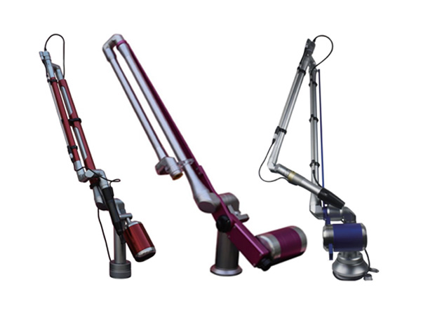
XY deflection units for deflection and focusing of laser beams in two dimensions for a variety of applications that require small to medium sized fields and high processing speeds.
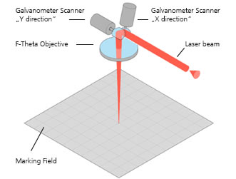
Our LSRL series 2-axis deflection units can be used to deflect a laser beam in X and Y directions. This produces a two-dimensional area allowing a laser to be directed at any position. This area is known as the “marking field” as shown in the diagram. Deflection is performed by two mirrors, each of which is moved by a galvanometer scanner. The deflection unit has a beam input, into which the laser beam is fed, and a beam output, through which a laser beam is emitted from the unit after deflection.
List of LSRL Series Laser Marking Heads
| Product series | Features | Available apertures |
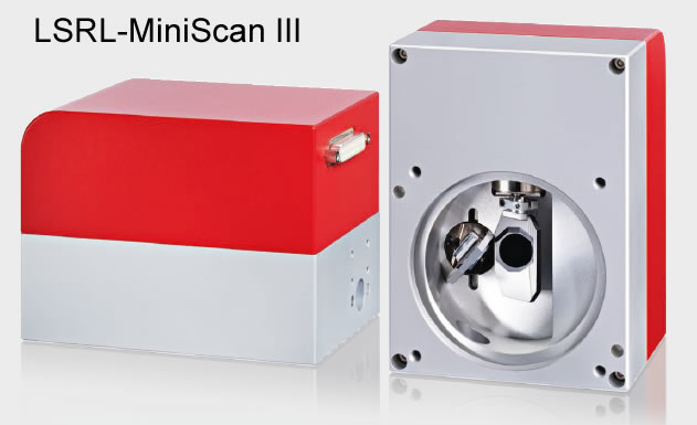
| MINISCAN II | Compact design and optimized performance. 50% less drift values. | 7, 10, 14 and 20 mm |
| MINISCAN III | Compact and robust design with digital control. | 10, 14 and 20 mm |
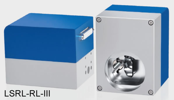
| RL III | For cost saving industrial designs | 10 and 14mm |
| SUPERSCAN IIE | Deflection unit for demanding laser applications. 50% better long-term drift. | 7, 10, 12, 15, 20 and 30 mm |
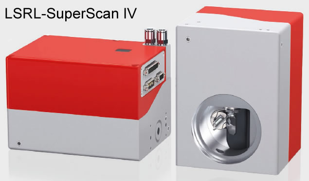
| SUPERSCAN IV | Full digital electronics. Highly dynamic and maximum speed up to 200 rad/s. | 10, 15, 20 and 30 mm |
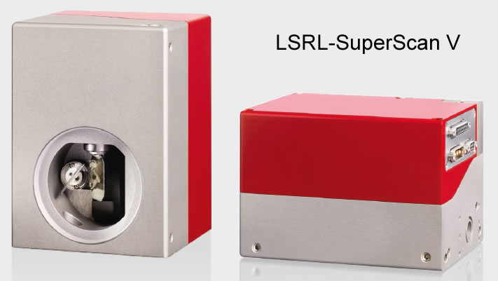
| SUPERSCAN V | Digital feedback control electronics. Excellent dynamics and monitoring of essential parameter in deflection unit. | 15 and 30 mm |
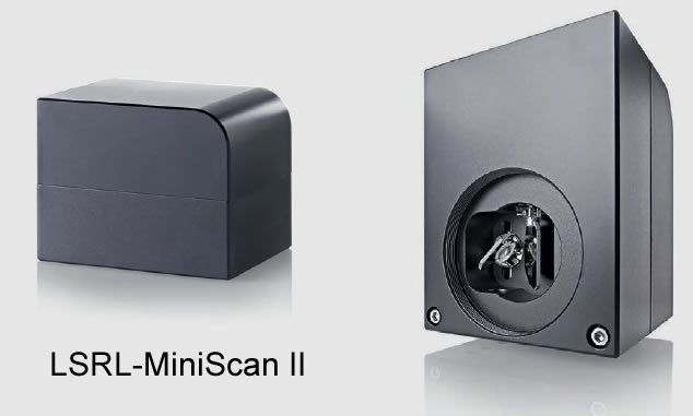
Very low drift
Extreme compact design
Robust and dust proof for industrial conditions
Insensitive to external temperature conditions
Available input apertures: 7, 10, 14, 20 mm
MINIMUM SIZE, MAXIMUM PERFORMANCE.
YOUR BENEFITS: The MINISCAN II is the new generation of scan heads with compact design and the performance optimized to achieve 50% less drift values. Its completely dust proof housing cover makes the MINISCAN II perfect for working in rough industrial conditions.
INNOVATION AND QUALITY: Innovation and maintaining high product quality standards are our priorities. All our products are developed, built and tested in our own laboratories and production facilities. Through our world-wide support network we can offer best maintenance and rapid service for our customers.
MIRRORS AND OBJECTIVES: Scan mirrors and objectives with optimized mounts are available for all typical laser types, wavelengths, power densities, focal lengths, and working fields. Customer specific configurations are also possible.
INTERFACES: The deflection units are compatible to the XY2-100 standard protocol. They can be controlled digitally by a control card, such as the SP-ICE-1 PCI PRO or via an analog current or voltage interface.
TYPICAL APPLICATIONS: Material processing such as marking, drilling, cutting, welding, hardening, texturing.
OPTION: We offer a camera adapter for process monitoring.
General Specifications:
Power supply: Voltage ±15 V to ±18 V; Current 2 A, RMS, max. 10 A; Ripple / Noise Max. 200 mVpp, @ 20 MHz bandwidth
Interface signals: Analog ±5 V, ±10 V; Digital XY2-100 protocol
Ambient temperature: +15°C to +35 °C
Storage temperature: -10°C to +60 °C
Humidity: ≤ 80 % non-condensing
Typical deflection (optical): ± 0.393 rad
Resolution: 12 μrad
Repeatability (RMS): 2 μrad
Max. Gaindrift1: 15 ppm/K
Max. Offsetdrift1: 10 μrad/K
Long-term drift1, 2: < 150 μrad
Remark: 1. Drift per axis. 2. After 30 min warm-up, at operating temperature, variations of ambient temperature <1K.
| Deflection unit | LSRL-MS-II-7 | LSRL-MS-II-10 | LSRL-MS-II-14 | LSRL-MS-II-20 |
| Mechanical data: | ||||
| Max. input beam diameter (mm) | 7.0 | 9.0 | 14.0 | 20.0 |
| Beam displacement (mm) | 9.0 | 12.4 | 17.0 | 26.0 |
| Weight (without objective) (kg) | approx. 0.8 | approx. 0.8 | approx. 1.6 | approx. 2.2 |
| Dimension (L x W x H) (mm) | 100.0 x 77.0 x 79.5 | 100.0 x 77.0 x 77.5 | 134.0 x 98.0 x 93.5 | 145.0 x 116.0 x 103.5 |
| Dynamic data: | ||||
| Acceleration time (ms) | 0.19 | 0.23 | 0.50 | 0.70 |
| Writing speed (cps)1, 2 | 900 | 500 | 400 | 300 |
| Processing speed (m/s)1 | > 10 | 7 | 6 | 5 |
| Positioning speed (m/s)1 | > 10 | 7 | 6 | 5 |
Remark: 1. With F-Theta Lens f = 163 mm / field size 120 mm x 120 mm. 2. Single-stroke font with 1 mm height.
Control via SL2-100 protocol 20 bit or XY2-100 protocol 16 bit
Digitally controlled, low noise and drift
Robust and dust-proof for industrial applications
Various mirror substrates and coatings for marking and cleaning
Input aperture: 10, 14 and 20mm
DIGITALLY CONTROLLED FOR HIGHEST MARKING SPEEDS
YOUR BENEFITS: The new MINISCAN III offers very stable digital control, which further improves noise and drift values, thereby making the system even more reliable and robust. Both the XY2-100 16 bit and the SL2-100 20 bit protocols can be used with the digital interface. A corresponding cable defines the use of the protocol.
CONFIGURABLE THROUGH AND THROUGH: Lenses, protective glass, and mirror substrates and coatings are available for many standard laser types, wavelengths, power densities, focal lengths and processing areas. This allows to handle a wide range of tasks with best quality and optimized throughput. We would also be happy to help you put together the perfect configuration for your application.
TYPICAL APPLICATIONS: Natural applications include ablation and cleaning of surfaces at high speed and challenging marking tasks. Speed and dynamic responses are guaranteed, thanks to digital control and powerful PWM output stages. You also have the option of combining the MINISCAN III with our CAMERA ADAPTER and MACHINE VISION CONTROL components for process monitoring.
INNOVATION AND QUALITYL Innovation and maintaining high product quality standards are our priorities. All our products are developed, built and tested in our own laboratories and production facilities. Through our world-wide support network we can offer best maintenance and rapid service for our customers.
General Specifications:
Power supply: Voltage ±30V or ±48 V; Current 2A, RMS, max. 5A; Ripple / Noise Max. 200 mVpp, @ 20 MHz bandwidth
Ambient temperature: +15°C to +35 °C
Storage temperature: -10°C to +60 °C
Humidity: ≤ 80 % non-condensing
IP-Code: IP64
Interface signals: Digital: XY2-100-Enhanced protocol; SL2-100 protocol
Typical deflection (optical): ± 0.393 rad
Resolution XY2-100 16-Bit: 12 μrad
Resolution SL2-100 20-Bit: 0.76 μrad
Repeatability (RMS): < 2.0 μrad
Position noise (RMS): < 4.5 μrad
Max. Gaindrift1: 15 ppm/K
Max. Offsetdrift1: 10 μrad/K
Long-term drift1, 2: < 80μrad
Remark: 1. Drift per axis. 2. After 30 min warm-up, at operating temperature, variations of ambient temperature <1K
Specifications of LSRL-MINISCAN III-10
| Part number | LSRL-MS-III-10 SI | LSRL-MS-III-10 QU |
| Input aperture (mm) | 10 | 10 |
| Beam displacement (mm) | 12.4 | 12.4 |
| Weight (without objective) (kg) | approx. 0.9 | approx. 0.9 |
| Dimension (L x W x H) (mm) | 100.0 x 77.0 x 83 | 100.0 x 77.0 x 81.5 |
| Tuning | MA | MA |
| Writing speed with high/good writing quality (cps) 1, 2 | 800 / 1,000 | 800 / 1,000 |
| Processing speed (rad/s) | 30 @ 30 V / 48 V | 30 @ 30 V / 48 V |
| Positioning speed (rad/s) 3 | 60 @ 30 V 100 @ 48 V | 60 @ 30 V 100 @ 48 V |
| Tracking error (ms) 4 | 0.13 | 0.13 |
| Step response time at 1% of full scale (ms) 5 | 0.30 | 0.30 |
| Wavelength | 355 nm SI; 532 nm SI; 1,064 nm SI; 1,070 nm QU; 10,600 nm SI (QU = quartz; SI = silicon) | |
Remark: 1. With F-Theta Lens f = 163 mm / field size 120 mm x 120 mm. 2. Single-stroke font with 1 mm height. 3. See “Calculation of speed”. 4. Calculation acceleration time approx. 1.8 x tracking error. 5. Setting to 1/1,000 of full scale. 6. Marking-Tuning (MA) Optimized tuning for marking applications
Calculation of speed
Speed in working field = Focal length F-Theta lens x Positioning speed:
Example: MINISCAN III-10 SI with F-Theta Lens f = 163 mm, Positioning speed 100 rad/s v = 163/1000 x 100 = 16 m/s
Mirrors and Lenses: Scan mirrors and objectives with optimized mounts are available many all typical laser types, wavelengths, power densities, focal lengths and working fields. Customer specific configurations are also possible.
Specifications of LSRL-MINISCAN III-14
| Part number | LSRL-MS-III-14 SI | LSRL-MS III-14 QU | ||||
| Input aperture (mm) | 14 | 14 | ||||
| Beam displacement (mm) | 17.0 | 17.0 | ||||
| Weight (without objective) (kg) | 2.0 | 2.0 | ||||
| Wavelength | 355 nm SI; 532 nm SI; 1,064 nm SI; 10.600 nm SI; 1.070 nm QU (QU = quartz; SI = silicon) | |||||
| Dimension (L x W x H) (mm) | 134.0 x 98.0 x 100.3 | 134.0 x 98.0 x 100.3 | ||||
| Tuning | VC | MA | C | MA | ||
| Writing speed (cps) with high/good writing quality ¹, ² | - | 650/800 | - | 600/750 | ||
| Processing speed (rad/s) ³ | 30 @ 30 V 50 @ 48 V | 30 @ 30 V 30 @ 48 V | 70 @ 30 V 100 @ 48 V | 30 @ 30 V 30 @ 48 V | ||
| Positioning speed (rad/s) ³ | 30 @ 30 V 50 @ 48 V | 60 @ 30 V 90 @ 48 V | 70 @ 30 V 100 @ 48 V | 60 @ 30 V 90 @ 48 V | ||
| Tracking error (ms) | 0.20 4 | 0.16 5 | 0.30 6 | 0.17 5 | ||
| Step response time at 1% of full scale (ms) | 0.68 7 | 0.36 8 | 0.69 7 | 0.39 8 | ||
Remark: 1. With F-Theta Lens f = 163 mm / field size 120 mm x 120 mm. 2. Single-stroke font with 1 mm height. 3. See “Calculation of speed”. 4. Calculation acceleration time approx. 2.3 x tracking error. 5. Calculation of acceleration time approx. 1.9 × tracking error. 6 Calculation of acceleration time approx. 2.0 × tracking error. 7. Setting to 1/5,000 of full scale. 8. Setting to 1/1000 of full scale. 9. Tuning is Vector-Tuning (VC) (Optimized tuning for a wide range of applications with emphasis on processing speed; Marking-Tuning (MA) (Optimized tuning for marking applications; Cleaning-Tuning (C) (Optimized tuning for long vectors at highest speeds.
Specifications of LSRL-MINISCAN III-20
| Part number | LSRL-MS-III-20 SI | LSRL-MS-III-20 QU |
| Input aperture (mm) | 20 | 20 |
| Beam displacement (mm) | 26.0 | 26.0 |
| Weight (without objective) (kg) | 2.5 | 2.5 |
| Dimension (L x W x H) (mm) | 145.0 × 116.0 × 103.5 | 145.0 × 116.0 × 103.5 |
| Tuning | M | M |
| Processing speed (rad/s) ¹ | 30 | 30 |
| Positioning speed (rad/s) ¹ | 30 | 30 |
| Tracking error (ms) ² | 0.30 | 0.34 |
| Step response time at 1% of full scale (ms) ³ | 0.90 | 1.01 |
| Wavelengths | 1,064 nm SI; 900 – 1,100 nm + AL SI; 10,600 nm SI; 515 – 540 nm QU; 1,060 – 1,090 nm + AL QU | |
Remark: 1. See “Calculation of speed”. 2. Calculation acceleration time approx. 2.3 tracking error. Setting to 1/5,000 of full scale. 4. Micro-structuring-Tuning (M): Optimized tuning for high precision beam deflection with sharp corners and minimized tracking error
Robust, compact and lightweight
Low noise and drift based on latest Servo-Electronic
Very high writing speed
Excellent price-performance ratio
Input aperture: 10 and 14mm
DIGITALLY CONTROLLED FOR HIGHEST WRITING SPEEDS
YOUR BENEFITS: The new RL-III offers you a very high writing and positioning speed at an outstanding price-performance ratio. Nevertheless, due to its low noise and drift values and its robustness, the system is ideally suited for use in an industrial production environment.
CONFIGURABLE THROUGH AND THROUGH: Lenses and protective glass are available for many standard laser types, the wavelengths 1,064 nm and 10,600 nm, power densities, focal lengths and processing areas. This allows to handle a wide range of tasks with high quality and optimized throughput. We would also be happy to help you put together the perfect configuration for your application.
TYPICAL APPLICATIONS: Dynamic marking tasks, especially on the fly, are predestined applications. Speed and dynamic responses are guaranteed, thanks to the new developed control with powerful PWM output stages.
INNOVATION AND QUALITY: Innovation and maintaining high product quality standards are our priorities. All our products are developed, built and tested in our own laboratories and production facilities. Through our world-wide support network we can offer best maintenance and rapid service for our customers.
General Specifications:
Power supply: Voltage +/-15 V to +/-18 V; Current 2 A, RMS, max. 10 A; Ripple/Noise Max. 200 mVpp@ 20 MHz bandwidth
Ambient temperature: +15°C to +35°
Storage temperature: -10°C to +60°C
Humidity: ≤ 80 % non-condensing
IP-Code: IP 54
Interface signals: Digital XY2-100 protocol
Typical deflection (optical): ± 0.393 rad
Resolution: XY2-100 16-Bit 12 μrad
Repeatability (RMS): < 2.0 μrad
Temperature drift: Max. Gaindrift(1) 15 ppm/K; Max. Offsetdrift(1) 10 μrad/K
Long-term drift 8 h1 < 150 μrad
Remark: 1. Angles optical. Drift per axis, after 30 min warm-up, at constant ambient temperature and process stress.
Specifications of RL-III-10 Scanner
Part number: LSRL-RL-III-10
Input aperture (mm): 10
Beam displacement (mm): 12.4
Weight (without objective) (kg): approx. 0.9
Dimension (L x W x H) (mm): 100.0 x 77.0 x 83
Wavelength: 1064 (nm) SI; 10600 (nm) SI (SI = silicon)
Tuning: Marking-Tuning (MA): Optimized tuning for marking applications
Writing speed with high/good writing quality (cps) (1, 2): 650 / 850
Processing speed (rad/s): 30
Positioning speed (rad/s) (3): 85
Tracking error (ms) (4): 0.14
Step response time at 1% of full scale (ms) (5): 0.40
Remark: 1. With F-Theta lens f = 163 mm / field size 120 mm x 120 mm. 2. Single-stroke font with 1 mm height. 3. See “Calculation of speed”. 4 Calculation acceleration time approx. 1.9 x tracking error. 5. Setting to 1/1,000 of full scale.
Lowest drift values through twin-shell design
Suitable for high power applications
Water tempering and air flushing options
“enhanced“ option for 50 % improved long-term drift
Available input apertures: 7, 10, 12, 15, 20, 30 mm
HIGHEST PRECISION WITH EXTREME PERFORMANCE
YOUR BENEFITS: The innovative thermal management and modular design make the SUPERSCAN IIE the perfect deflection unit for demanding laser applications. The “enhanced” option offers a 50 % better long-term drift performance. Long-term drift can even be further minimized by an additional water tempering.
MIRRORS AND OBJECTIVES: Scan mirrors and objectives with optimized mounts are available for all typical laser types, wavelengths, power densities, focal lengths and working fields. Customer specific configurations are also possible.
INTERFACES: The deflection units are compatible to the XY2-100 standard. They can be digitally controlled by a control card, such as the SP-ICE-1 PCIe PRO.
TYPICAL APPLICATIONS: Material processing such as engraving, marking, ablation, cutting, welding, perforating, or high speed processing on the fly. The water tempered option is extremely suitable for very precise application requirements with low tolerance such as micro machining, drilling, ITO structuring or Ag-patterning.
INNOVATION AND QUALITY: Innovation and maintaining high product quality standards are our priorities at RAYLASE. All our products are developed, built and tested in our own laboratories and production facilities. Through our world-wide support network we can offer best maintenance and rapid service for our customers.
General Specifications
Power supply: Voltage ± 15 V to ± 18 V; Current 3 A, RMS, max. 10 A; Ripple/Noise Max. 200 mVpp@ 20 MHz bandwidth
Interface signals: Digital XY2-100 protocol
Ambient temperature: +15°C to +35°C
Storage temperature: -10°C to +60°C
Humidity: ≤ 80 % non-condensing
Temperature Drift: Max. Gaindrift (1): < 15 ppm/K; Max. Offsetdrift (1): < 10 μrad/K
Typical deflection (optical): ± 0.393 rad
Resolution optically: 12 μrad
Repeatability (RMS): 2 μrad
Long-term Drift 8 h (1, 2): < 150 μrad
Long-term Drift 8 h water tempering (1, 2): < 100 μrad
Position noise (RMS): < 10 μrad
Remark: 1. Drift per axis. 2. After 30 min warm-up, at constant ambient temperature and process stress. 3. After 30 min warm-up, under varying process loads, with water temperature control set for ≥ 2 l/min and 22˚C water temperature.
| Part number | LSRL-SS-IIE-7 | LSRL-SS-IIE-10 | LSRL-SS-IIE-12 | LSRL-SS-IIE-15 | LSRL-SS-IIE-20 | LSRL-SS-IIE-20 L | LSRL-SS-IIE-30 |
| Input aperture (mm) | 7 | 10 | 12 | 15 | 20 | 20 | 30 |
| Beam displacement (mm) | 9.0 | 12.4 | 14.0 | 18.55 / 18.05 (1) | 26.28 / 25.63 (1) | 26.28 / 25.63 (1) | 35.98 / 35.38 (1) |
| Weight (without objective) (kg) | approx. 1.6 | approx. 3.3 | approx. 3.3 | approx. 3.3 | approx. 3.3 | approx. 5.9 | approx. 5.9 |
| Dimension (L x W x H) (mm) | 135x97x 102.0 | 170x125x 117.5 | 170x125x 117.5 | 170x125x 117.5 | 170x125x 117.5 | 203 x 159 x 150/160.5 (2) | 203x159x 150/160.5 (2) |
| Water temperature option | √ | √ | √ | √ | √ | √ | |
| Air flushing option | √ | √ |
Remark: 1. Specification for fused silica mirrors. 2. AXIALSCAN variation only, additional output plate for protection window
Mirror Variations
| Part number | LSRL-SS-IIE-7 | LSRL-SS-IIE-10 | LSRL-SS-IIE-12 | LSRL-SS-IIE-15 | LSRL-SS-IIE-20 | LSRL-SS-IIE-30 |
| 355 nm | SI | SI | SI | QU, SI | QU | |
| 532 nm | SI | SI | SI | QU, SI | QU, SI | QU |
| 780–980nm+AL | QU | QU | QU | |||
| 1064 nm | SI | SI | SI | QU, SI | QU, SI | QU, SI, SC |
| 900–1100nm+AL | SC | |||||
| 1020–1040nm | QU | |||||
| 1060–1080nm | QU, SC | |||||
| 10600nm | SI | SI | SI | SI, SC | SI | SI, SC |
Remark: Standard: QU = Quartz (Fused Silica), SI = Silicon, High Speed: SC = Silicon carbide
Dynamic Data
| Part number | LSRL-SS-IIE-7 | LSRL-SS-IIE-10 | LSRL-SS-IIE-12 | LSRL-SS-IIE-15 | ||
| Mirror type | SI | SI | SI | QU | SI | SC |
| Acceleration time (ms) | 0.19 | 0.22 | 0.25 | 0.36 | 0.30 | 0.24 |
| Writing speed (cps) ¹, ² | 900 | 800 | 650 | 450 | 500 | 650 |
| Processing speed (rad/s) ¹ | 90 | 60 | 50 | 35 | 40 | 50 |
| Positioning speed (rad/s) ¹ | 90 | 60 | 50 | 35 | 40 | 50 |
| Part number | LSRL-SS-IIE-20 / SS-IIE-20 L | LSRL-SS-IIE-30 | |||
| Mirror type | QU | SI | QU | SI | SC |
| Acceleration time (ms) | 0.70 | 0.61 | 0.90 | 0.84 | 0.52 |
| Writing speed (cps) ¹, ² | 350 | 350 | - | - | - |
| Processing speed (rad/s) ¹ | 35 | 35 | 25 | 30 | 35 |
| Positioning speed (rad/s) ¹ | 35 | 35 | 25 | 30 | 35 |
Remark: 1. With f-theta lens f = 160 mm / field size 110 mm x 110 mm. 2. Single-stroke font with 1 mm height.
Control via SL2-100 protocol 20 bit or XY2-100 protocol 16 bit
Digital driver board (PWM) with significantly reduced power loss and minimal heat development
Dynamic responses and high speeds for maximum productivity
Several tunings and mirror coatings for diverse applications
Input aperture: 10, 15, 20 and 30mm
DYNAMIC, FAST AND VERSATILE
YOUR BENEFITS: The SUPERSCAN IV‘s model-based, digital control offers extremely dynamic responses and speeds, which really come into play in marking – and extreme fast, but precise structuring-, cutting- and drilling-applications. The robust, water-cooled master block design guarantees stable and low drift operation even with frequent beam direction change and high jump frequencies.
CONFIGURABLE THROUGH AND THROUGH: Lenses, protective glass, and mirror coatings are available for all standard laser types, wavelengths, power densities, focal lengths and processing areas. This allows to handle a wide range of tasks with best quality and optimized throughput. We would also be happy to help you put together the perfect configuration for your application.
TYPICAL APPLICATIONS:Demanding code-marking, cutting of FPC-structures as well as drilling of copper-foils are natural applications for the SUPERSCAN-IV. Speed and dynamic responses are guaranteed, thanks to digital control and powerful PWM output stages. When combined with our camera adapter and MVC components, the SUPERSCAN IV becomes the ideal precision tool with process monitoring.
INNOVATION AND QUALITY: Innovation and maintaining high product quality standards are our priorities. All our products are developed, built and tested in our own laboratories and production facilities. Through our world-wide support network we can offer best maintenance and rapid service for our customers.
General Specifications
Power supply: Voltage 30 V or 48 V; Current 2 A RMS, max. 5 A; Ripple/Noise Max. 200 mVpp@20 MHz bandwidth
Ambient temperature: +15°C to +35°C
Storage temperature: -10°C to +60°C
Humidity: ≤ 80 % non-condensing
IP Code: 64
Interface signals: Digital XY2-100-Enhanced protocol; Digital SL2-100 protocol
Typical deflection: ± 0.393 rad
Resolution: XY2-100-E 16-Bit 12 μrad; Resolution SL2-100 20-Bit 0.76 μrad
Repeatability (RMS): < 2.0 μrad
Position noise (RMS): < 4.5 μrad
Temperature Drift: Max. Gaindrift ¹ 15 ppm/K; Max. Offsetdrift ¹ 10 μrad/K
Long-term drift 8 h without water temperature control ¹ : < 60 μrad
Long-term drift 8 h with water temperature control ¹, ² : < 40 μrad
Remark: 1. Angles optical. Drift per axis, after 30 min warm-up, at constant ambient temperature and process stress. 2. After 30 min warm-up, under varying process loads, with water temperature control set for ≥ 2 l/min and 22˚C water temperature.
Specifications of LSRL-SS-IV Series
Part number: LSRL-SS-IV-10
Input aperture (mm): 10
Beam displacement (mm): 12.5 (SI)
Weight (without objective) (kg): approx. 3.2
Dimension (L x W x H) (mm): 170.0 x 125.0 x 117.5
Wavelength: 355, 532 and 1064nm, Silicon
Tuning: Vector tuning (VC) (Optimized tuning for a wide range of applications with emphasis on processing speed) and M-Tuning (M) (Optimized tuning for high precision beam deflection with sharp corners and minimized tracking error)
| Part number | LSRL-SS-IV-10-SI | |
| Tuning | VC | M |
| Processing speed (rad/s) ¹ | 50 @ 30 V 80 @ 48 V | 30 @ 30 V 30 @ 48 V |
| Positioning speed (rad/s) ¹ | 50 @ 30 V 80 @ 48 V | 30 @ 30 V 30 @ 48 V |
| Tracking error (ms) | 0.12 3 | 0.10 4 |
| Step response time at 1% of full scale (ms) ² | 0.33 | 0.41 |
Remark: 1. See “Calculation of speed”. 2. Settling to 1/5,000 of full scale. 3. Calculation acceleration time approx. 1.9 x tracking error. 4. Calculation of acceleration time approx. 1.8x tracking error
Options:
The SUPERSCAN IV-10 deflection units provide water temperature control (W) for the electronic components and galvanometer scanners. This ensures constant working conditions and excellent long-term stability, thus guaranteeing reliable operation even in high power laser applications. The SUPERSCAN IV-10 deflection units can also be operated without temperature control (N). In consequence the drift values may increase.
Specifications of LSRL-SS-IV-15 Series
Part number: LSRL-SS-IV-15
Input aperture (mm): 15
Beam displacement (mm): 18.1 (QU, SI), 18.0 (SC)
Weight (without objective) (kg): approx. 3.2
Dimension (L x W x H) (mm): 170.0 x 125.0 x 117.5
Wavelength and substrate: 355 nm QU; 532 nm QU, SI; 1030 nm SC; 1064 nm QU, SI, SC; 1060nm–1080 nm (high power coating) QU; 10600 nm SI, SC (QU = quartz; SC = silicon carbide, SI = Silicon)
Tuning: Vector tuning (VC) (Optimized tuning for a wide range of applications with emphasis on processing speed), C-Tuning (C) (Optimized tuning for long vectors at highest speeds) and Hatching Tuning (H) (Optimized tuning for high precision beam deflection and fastest beam direction change during hatching)
| Part number | LSRL-SS-IV-15-QU | LSRL-SS--IV-15-SI | S LSRL-SS-IV-15-SC | ||
| Tuning | VC | C | VC | VC | H |
| Processing speed (rad/s) (1) | 45 @ 30 V; 50 @ 48 V | -200 @ 48 V | 50 @ 30 V; 65 @ 48 V | 55 @ 30 V; 75 @ 48 V | 30 @ 30 V; 30 @ 48 V |
| Positioning speed (rad/s) (1) | 45 @ 30 V; 50 @ 48 V | -200 @ 48 V | 50 @ 30 V; 65 @ 48 V | 55 @ 30 V; 75 @ 48 V | 30 @ 30 V; 30 @ 48 V |
| Tracking error (ms) | 0.19 (3) | 0.30 (4) | 0.16 (3) | 0.14 (3) | 0.12 (3) |
| Step response time at 1% of full scale (ms) (2) | 0.49 | 0.65 | 0.43 | 0.37 | 0.47 |
Remark: 1. See “Calculation of speed”. 2. Setting to 1/5,000 of full scale. 3. Calculation acceleration time approx. 1.9 x tracking error. 4. Calculation of acceleration time approx. 2.3 x tracking error
Specifications of LSRL-SS-IV-20 Series
Part number: LSRL-SS-IV-20 QU
Input aperture (mm): 20
Beam displacement (mm): 26.0
Weight (without objective) (kg): approx. 5.5
Dimension (L x W x H) (mm): 203.0 x 159.0 x 150.0 / 160.5 (1)
Wavelengths and substrate: 355 nm QU, SC; 532 nm QU, SC; 1,064 nm QU, SC
Vector tuning (VC): Optimized tuning for a wide range of applications mainly focused on processing speed, other tunings on request
Remark: 1. AXIALSCAN model, output plate for protection window.
| Part number | LSRL-SS-IV-20-QU | LSRL-SS-IV-20-SC |
| Tuning | VC | VC |
| Positioning speed (rad/s) ¹ | 45 @ 30 V 55 @ 48 V | 50 @ 30 V 75 @48 V |
| Tracking error (ms) 2 | 0.3 | 0.22 |
| Step response time at 1% of full scale (ms) 3 | 0.7 | 0.5 |
Remark: 1. See “Calculation of speed”. 2. Calculation acceleration time approx. 1.7 x tracking error. 3. Settling to 1/5,000 of full scale.
Positioning of the laser with 20 bit resolution with the SL2-100 protocol
Minimal drift and extremely low noise thanks to digital encoder technology
Extreme acceleration and precise laser guidance for sharp corners and edges
Recording and diagnosis of all properties
Input aperture: 15 and 30mm
FULLY DIGITAL FEEDBACK CONTROL, FAST AND PRECISE
General Specifications
Power supply: Voltage 30 V or 48 V; Current 2 A RMS, Max. 5 A; Ripple/Noise Max. 200 mVpp@ 20 MHz bandwidth
Ambient temperature: +15 °C to +35 °C
Humidity: ≤ 80 % non-condensing
IP-Code: 65
Interface signals: Digital XY2-100-Enhanced protocol Digital SL2-100 protocol
Typical deflection: ± 0.393 rad
Resolution: XY2-100-E 16-Bit 12 μrad
Resolution: SL2-100 20-Bit 0.76 μrad
Repeatability (RMS): < 0.4 μrad
Position noise (RMS): < 2.0 μrad
Temperature drift: Max. Gaindrift ¹ 8 ppm/K; Max. Offsetdrift ¹ 15 μrad/K
Long-term drift 8 h without water tempering ¹: < 50 μrad
Long-term drift 8 h with water tempering ¹, ²: < 30 μrad
Mirrors & Lenses: Scan mirrors and objectives with optimized mounts are available for all typical laser types, wavelengths, power densities, focal lengths and working fields. Customer specific configurations are also possible.
Options: The SUPERSCAN V deflection unit provides two types of water temperature control (W) for the electronic components and galvanometer scanners, straight (W) connectors and 90° (W2). This ensures constant working conditions and excellent long-term stability.
Specifications of LSRL-SS-V-15
Input aperture (mm): 15
Beam displacement (mm): 18.27 (SC), 18.33 (QU)
Weight (without objective) (kg): approx. 3.2
Dimension (L x W x H) (mm): 170.0 x 125.0 x 117.5
Wavelengths and substrates: 355 nm SC, QU; 405 nm QU; 532 nm SC, QU; 1,064 nm SC, QU; 10600 nm SC; AG SC
Micro-structuring tuning: Optimized for high precision beam deflection with sharp corners and minimized tracking error
| Deflection unit | LSRL-SS-V-15-QU | LSRL-SS-V-15-SC |
| Mirror type | QU | SC |
| Tuning | Micro-structuring | Micro-structuring |
| Writing speed (cps) ¹ | 600 | 800 |
| Processing speed (rad/s) ² | 30 | 30 |
| Positioning speed (rad/s) ² | 30 | 30 |
| Tracking error (ms) ³ | 0.18 | 0.14 |
| Step response time 1 % of full scale (ms) 4 | 0.55 | 0.45 |
Remark: 1. With F-Theta lens f = 163 mm / field size 120 mm x 120 mm, Single-stroke font with 1 mm height. 2. See “Calculation speed”. 3. Calculation acceleration time approx. 1.7 × tracking error. 4. Setting to 1/5,000 of full scale.
Specifications of LSRL-SS-V-30
Input aperture (mm): 30
Beam displacement (mm): 35.7
Weight (without objective) (kg): approx. 5.5
Dimension (L x W x H) (mm): 203.0 x 159.0 x 150.0
Wavelengths and substrates: 1064 nm SC; 10600 nm SC
Microstructuring tuning: Optimized tuning for high precision beam deflection with sharp corners and minimized tracking error.
Specifications of deflection unit LSRL-SS-V-30-SC
Mirror type: SC
Tuning Microstructuring
Processing speed (rad/s) ¹: 25 @ 30 V; 30 @ 48 V
Positioning speed (rad/s) ¹: 25 @ 30 V; 30 @ 48 V
Tracking error (ms) ²: 0.25
Step response time 1 % of full scale (ms) ³: 0.66
Remark: 1. See “Calculation of speed”. 2. Calculation acceleration time approx. 1.7 × tracking error. 3. Setting to 1/5,000 of full scale.
A leading supplier and manufacturer of a wide range of photonics products such as lasers,laser parts & machines.
Office: 10 Bukit Batok Crescent #07-02 The Spire Singapore 658079
Tel: +65 63167112
Fax: +65 63167113
Whatsapp: +65 91904616