CNC Control Card & Software

CNC Control Card & Software

Keywords: CNC, software, digital, CNC2000, cutting software
Feb 20, 2021 View: 3594 Data Sheet

Our CNC2000 control card and software can maximally support 6-axis control at the same time. It can be used in the numerical control system of 3-axis linear motion + 3-axis rotational motion (X,Y,Z,C,A,B) or 6-axis rotational motion (6-joint mechanica

CNC2000 Series Control Cards and Software

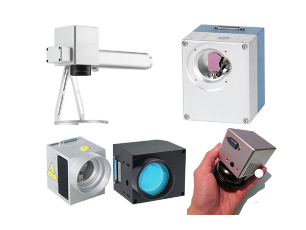
Our CNC2000 control card and software can maximally support 6-axis control at the same time.  It operates under Windows such as Win10, Win7, Win2000, WinXP, Windows98, WindowsSME or Windows95. It can be used in the numerical control system of 3-axis linear motion + 3-axis rotational motion (X,Y,Z,C,A,B) or 6-axis rotational motion (6-joint mechanical arm). Also it can control all the lasers in the market such as YAG lasers, CO2 lasers, fiber lasers and ultrafast lasers.

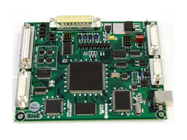
The CNC control card is an Ethernet card which is more convenient for connections. The advantages and features of the CNC control card are

  • Better stability, anti-interference and precision than traditional PCI card

  • More convenient for connections

  • No need to have a PCI slot to insert the control card

  • Operate in all versions of Windows systems

  • Operate in laptop or desktop computers

  • Can output 0-10V analogue voltage to achieve the real-time control of the fiber laser power

  • Can output 24V PWM signals to control the frequency and pulse width of the fiber lasers or CO2 lasers

  • One control card can support 6-axis system and combined 2 cards can support 10-12-axis system

  • The number of the input ports has been increased to 32 to achieve multi-station control and various kinds of logic control according to different input signals

Our control cards are made with multi-layer circuit boards and power source and ground are separated into two layers. Although the card costs more, they improve the performance of anti-interference. Thus our cards can be used in precise control.

Our software’s functions are strong and easy to operate. The programming is simple and easy. There are 3 methods to write a programming: automatic conversion of PLT and DXF files, teaching or CNC programming. The software programming panel is as follows:

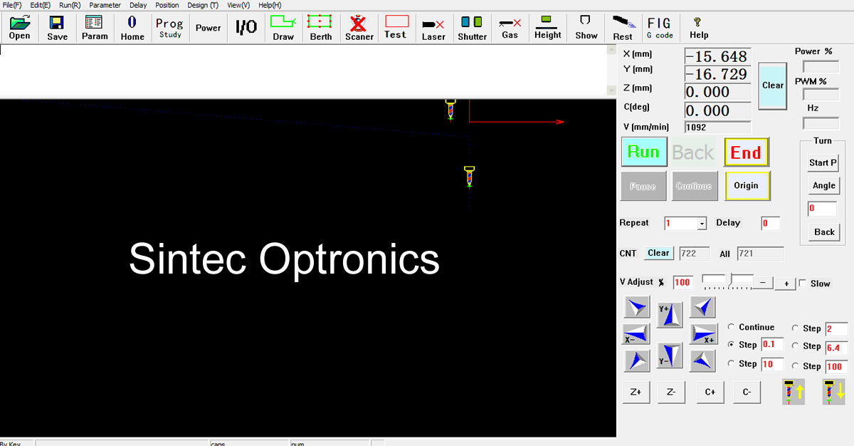
The main functions of the software programming are as follows:

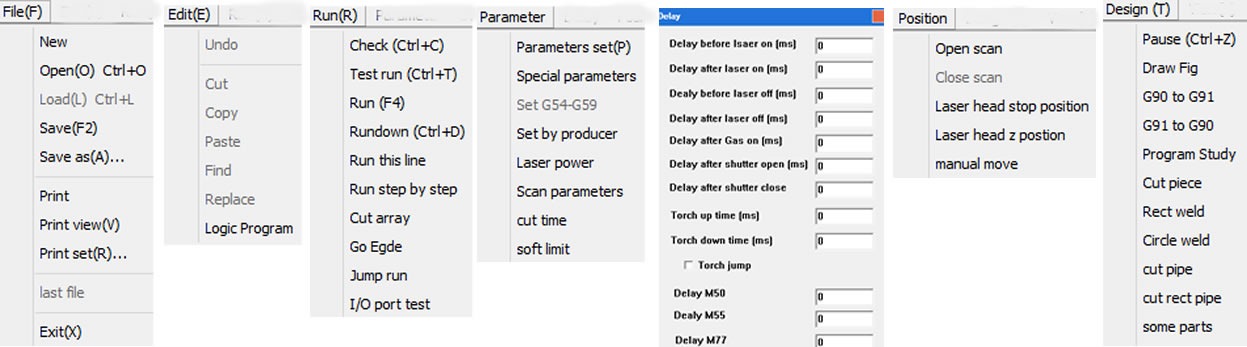
The main programming points are as follows:

  • Maximum axis: 6

  • Program verification function

  • MDI function

  • Absolute/increment programming (G90, G91)

  • Programming using inch, metric, pulse number (G20, G21, G22)

  • Mirror function (G24, G25)

  • Zoom (magnification/demagnification) (G50, G51)

  • Automatic, step, manual, home function

  • Fast position (G00), linear interpolation (G01)

  • Arc interpolation (G02, G03)

  • Pause (G04), screw thread function (G33)

  • Set/back zero (G29, G30)

  • Reverse clearance compensation, beam diameter compensation (G40, G41, G42)

  • Coordinate rotation (G68, G69)

  • Sub-function

  • Static/dynamic emulation

  • Max stepping frequency: 200000Hz

  • Automatic acceleration/deceleration

  • Automatic conversion of PLT and DXF files

Ordering Information

Part numberDescription
ST-CNC2000-4S4-axis control and to switch on/off laser beam such as YAG laser
ST-CNC2000-4M4-axis control and to fully control all types lasers such as YAG, CO2 or fiber lasers
ST-CNC2000-6S6-axis control and to switch on/off laser beam such as YAG laser
ST-CNC2000-6M6-axis control and to fully control all types lasers such as YAG, CO2 or fiber lasers

STAC Series CNC Control Boards & Software

1. STAC-MCC3721 Control Boards

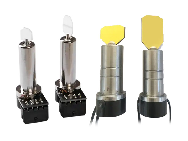
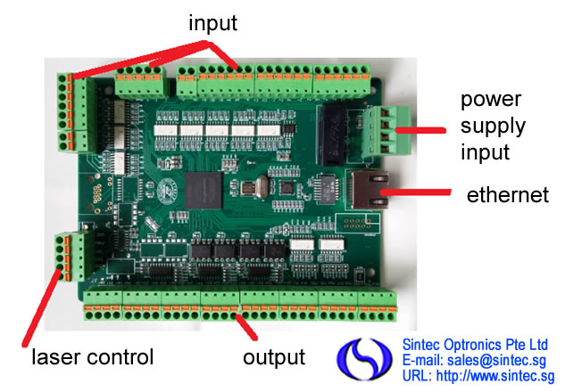
The control boards used to control lasers, laser cutting heads, XYZW motion and capacitor height sensor in the cutting heads. STAC-MCC3721H is to control XYZ 3-axis motion and STAC-MCC3721NC is to control XYZW 4-axis motion.

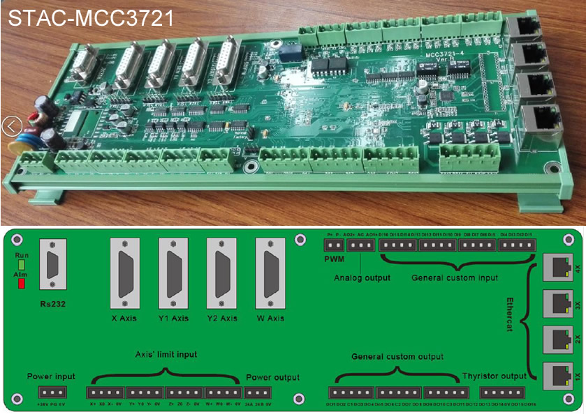
The I/O ports are defined as following table.

PortFunctionRemark
Power input+24VDC24V input + end24V/10A DC. Recommend to use DC 24V/10A power supply
PGprotective ground
0VDC input - end, power GND
Axis’ limit inputX+X Axis’ positive limit input, special signal, low-level propagation is effective.X Axis’ limit input
X0X Axis’ origin signal, special signal, low-level propagation is effective.
X-X Axis’ negative limit input, special signal, low-level propagation is effective.
0VGND, X Axis’ limit signal COM port
Y+Y Axis’ positive limit input, special signal , low-level propagation is effective.Y Axis’ limit input
Y0Y Axis’ origin signal, special signal, low-level propagation is effective. YY Axis’ negative limit input, special signal, low-level propagation is effective. 0V GND, Y Axis’ limit signal COM port
Y-Y Axis’ origin signal, special signal, low-level propagation is effective. YY Axis’ negative limit input, special signal, low-level propagation is effective. 0V GND, Y Axis’ limit signal COM port
0VY Axis’ origin signal, special signal, low-level propagation is effective. YY Axis’ negative limit input, special signal, low-level propagation is effective. 0V GND, Y Axis’ limit signal COM port
Z+Z Axis’ positive limit input, special
signal, low-level propagation is effective.
Z Axis (standby ) input
Z0Z Axis’ origin signal,special signal,low-level propagation is effective.
Z-Z Axis’ negative limit input,special signal,low-level propagation is effective.
0vGND, Z Axis’ limit signal COM port
W+W Axis’ positive limit input,special signal,low-level propagation is effective.W Axis(Rotation Axis / standby ) input
W0W Axis’ origin signal,W
W-W Axis’ negative limit input,special signal,low-level propagation is effective.
0vGND, W Axis’ limit signal COM port
Axis’ controlling portsXX Axis’ controlling signalDB15female
Y1Y1 Axis’ controlling signal
Y2(Z)Y2(Z)Axis’ controlling signalIf Y Axis is set up as dual - drive mode, it is Y2Axis; if Y Axis is set up as single drive mode, it is Z Axis’ controlling port( standby ).
WW Axis’ controlling signalRotation Axis( standby )
General custom outputsDO1DO1 general output portThe function of output port can be set up arbitrarily by software. Passive output port has the same output TTL with COM port.
DO2DO2 general output port
COM1general output COM port
DO3DO3 general output port
DO4DO4 general output port
DO5DO5 general output port
DO6DO6 general output port
COM2general output COM port
DO7DO7 general output port
DO8DO8 general output port
DO9DO9 general output port
DO10DO10 general output port
COM3General output COM port
DO11DO11 general output port
DO12DO12 general output port
Thyristor outputDO13DO13 thyristor output portDCV output: 24V, drive current: 1A
DO14DO14 thyristor output port
COM4Thyristor output COM port
DO15DO15 thyristor output port
DO16DO16 thyristor output port
Power output24AThe first DC24V output +endCan be used as Axis’ limit switch/general output port can supply standard TTL
24BThe 2nd DC24V output +end
0VThe GND for DC24V output
PWM outputP+PWM signal output +endThe TTL of PWM output is 24V/5, which can be configured by the jumper nearby.
P-PWM signal output -end
Analog outputAO1+Analog output port +endThe voltage of analog output is from 0V to 10V, which can be configured by software.
AGThe GND for analog output
AO2+Analog outpot port +end
AIAnalog input
General inputDI1general input port, low-level propagation is effective (Default)
DI2general input port, low-level propagation is effective (Default)
DI3general input port, low-level propagation is effective (Default)
DI4general input port, low-level propagation is effective (Default)
DI5general input port, low-level propagation is effective (Default)
DI6general input port, low-level propagation is effective (Default)
DI7general input port, low-level propagation is effective (Default)
DI8general input port, low-level propagation is effective (Default)
DI9general input port, low-level propagation is effective (Default)
DI10general input port, low-level propagation is effective (Default)
DI11general input port, low-level propagation is effective (Default)
DI12general input port, low-level propagation is effective (Default)
DI13general input port, low-level propagation is effective (Default)
DI14general input port, low-level propagation is effective (Default)
DI15general input port, low-level propagation is effective (Default)
0VSignal input public port
Ethernet1XIndustrial Ethernet interfaceThese four ports can be arbitrarily configured
2XIndustrial Ethernet interface
3XIndustrial Ethernet interface
4XIndustrial Ethernet interface
General serial portRS232RS232 serial portIt can butt-joint with laser

2. Laser Cutting Software STAC-SC2000

STAC-SC2000 CNC cutting software is designed for flat fiber laser cutting which includes graphic drawing and editing, cutting process dealing, cutting process controlling, system monitoring, components monitoring and debugging, and so on.

Features:

1) Simple Operations, Powerful Functions.

  • Developed based on RIBBON framework, the design is unique and the software is easy to be operated.

  • UI design is more humanized, which is easier to use even without training.

  • With powerful CAM functions based on AUTOCAD design, support graphic import, graphic drawing, graphic editing, and graphic transformation, graphic optimized and so on.

  • Intelligent capturing, which makes drawing more convenient and accurate.

  • Unique properties option design, which helps user to design the cutting graphic more easily.

  • Support various sort methods, auto sort can recognize the film inside or outside the graphic to make sure the path planning optimized.

  • Powerful lead line function, support various ways to lead line, auto added suitable lead line based on graphic nested relations. Support check/revise interfered lead line by one click.

2) Complete cutting process, debugging easily.

  • Support all kinds of cutting process: Section drill, gradual drill, multi stages drill, cutting with film, fix height cutting, and predrill and so on.

  • Support laser’s power/frequency adjusted with speed, to decrease or avoid the problem of firing corners when cutting carbon steel.

  • Support multilayer cutting or marking, and other sorts of processing ways.

  • Support micro-joint, gap, over-cutting, bridge, kerf-compensation and so on.

  • Powerful material database, which can save all sorts of material cutting process.

  • Support complex functions: Edge seeking, fly-cutting and so on.

  • Support breakdown position tracking/forward/backward and so on.

3) Rea-time alarm, stable and reliable.

  • Support running error measurement, it can check the error between running orbit and graphic error.

  • Real-time alarming the status of capacitive height controller, laser source, auxiliary gas of electric laser cutting head and other equipment, make sure the security during cutting.

  • More than 50 different kinds of alarms, to secure the equipment in whole aspect, avoid user’s wrong operation.

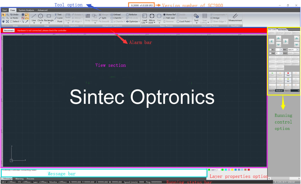
UI design is very clear, from up to down: title option, tool option, alarm option, view option, running control option, message bar, graphic parameters option, and status bar. The functions of each section shows as below:

SectionFunctionRemark
Tittle barDisplay software’s name and version number.
Tool optionMainly collects the tools needed for software
operation, it has five submenu:
Start/Draw/System Analysis/Advanced/Nest.
User can do graphic drawing, graphic editing,
graphic transformation, adding lead line,
monitoring running status, configuration
machine tool.
Alarm barDisplay the current system alarm.Alarm will be displayed in pop-up window, and once the alarm is cleared, the pop-up window will be gone.
View sectionGraphic drawing/displaying section, displaying section of the machine’s cutting area.
Running control
option
Run all kinds of cutting actions by software.
Message barDisplay the current running status in scrolling to attract user’s attention.
Layer properties
option
Set up layer properties such as layer process, graphic transformation and so on.
Running statusDisplay the running status, running location, cutting speed and so on.

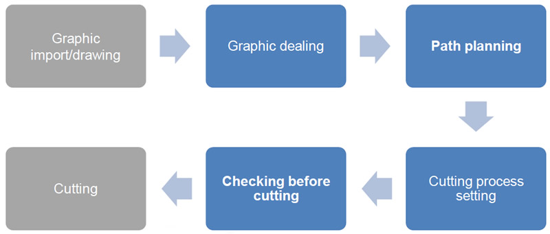
Operation flowchart:

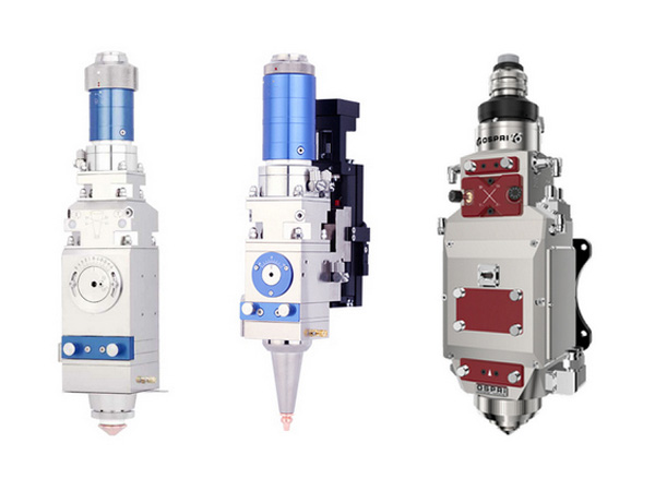
A full package consists of a laser cutting head, a control board and cutting software.

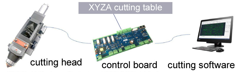
The functions of each part is summarized as following:

Part namePart number/combinationRemarks
Cutting headSTAC-A200MS<2kW, manual focusing
Cutting headSTAC-A200MS-3D<2kW, manual focusing, smaller 3D nozzle size for tube cutting
Cutting headSTAC-A260E<2kW, electrical focusing
Cutting headSTAC-A290E<2kW, electrical focusing, smaller 3D nozzle size for tube cutting
Cutting headSTAC-A280E<4kW, electrical focusing
Cutting headSTAC-A295E<4kW, electrical focusing, smaller 3D nozzle size for tube cutting
Control systemSTAC-MCC3721H + STAC-SC20003-axis (X, Y1, Y2, Z) flat-plate cutting. Y1 & Y2 have same signals.
Control systemSTAC-MCC3721NC + STAC-SC20004-axis (X, Y1, Y2, Z, A) flat-plate cutting. A is used to exchange tables.
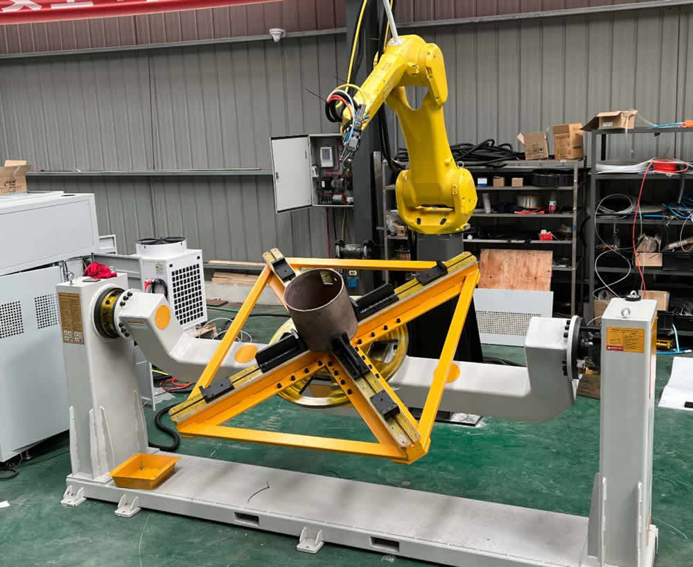
Control systemSTAC-MCC3723+STAC-FTC10+SCTubeTubing cutting such as round, square, L, H and rotation
Control systemSTAC-MCC3723+STAC-FTC10+STAC-EX15*2+SCTubeTubing & flat plate cutting
Total solutionSTAC-A200MS+STAC-3721H+STAC-SC2000Internal height floating, for thin flat plate cutting
Total solutionSTAC-A260E+STAC-MCC3721NC+STAC-SC2000Internal height floating and auto-focusing, for thick flat plate cutting
Total solutionSTAC-A200MS-3D+STAC-MCC3723+STAC-FTC10+STAC-SCTubeProfessional tubing cutting such as round, square, L, H and rotation
Height floatingSTAC-FTC10 (not including sensor nozzle)Individual height adjusting, for tubing, flat-plate, 3D cutting
Height floatingSTAC-FTC61 (not including sensor nozzle)Individual height adjusting, supporting pulse step or servo motors

STH Series CNC Motion Controllers and Software

1. STH-E1701C Modular 5-Axis CNC Controller

Beside common laser scanner controller cards STH-BeamConstruct also supports the only modular, 5-axis CNC controller card worldwide: the STH-E1701C. This is a low-cost CNC controller card with the smallest ground-size out there and it is the only one which can be extended by additional boards providing different signals and outputs. So it is not necessary to buy one fully featured card and to pay for functions that are not needed. Via its extension boards only these functions and I/Os can be added, that are really required.

Due to its future-proof design and its extensive interfaces and software options, it is not limited to laser applications, but it is also able to control mechanical tools such as mills. Our STH-BeamConstruct control application fully supports such machinery, beside the common laser parameters it is also able to handle the STH-E1701C and the specialities of such mechanical tools. These extension boards are plugged onto baseboard. Several of them can be combined freely according to required functionality.

laser marking software

STH-E1701C Baseboard is a 5-axis CNC controller card which can control lasers as well as other tools with suitable hardware interfaces. It can be extended by options described below and provides following features:

  • Support for up to 5 stepper motor axes which can be controlled via step/direction signals

  • Can be used with any XY-table/-gantry, XYZ-stage or similar 2..5-axis, motor-driven CNC devices

  • Fully synchronous movements of all axes for real 2D/3D/... operations

  • 100 Mbit Ethernet connection

  • USB 2.0 connection

  • Command execution time down to 0,5 microseconds

  • Realtime processing of laser and motion signals

  • CMOS level on/off output to toggle laser or tool

  • Can control nearly every laser type (this may require extension boards as described below)

  • Power ramping output to modulate laser power or tool speed during movements

  • CMOS level inputs to start or stop operations by hardware signal

  • 5 optionally opto-insulated reference-switch inputs which can be operated with up to 24 V external power

  • 512 MByte DDR3 RAM

  • 4-core system with 1 GHz clock on main CPU core

  • Extremely low power consumption of about 1,8 W (Baseboard without any Extension Boards)

  • Internal command and vector data list with more than 17 million entries

  • Continuous list concept, no need to swap between lists

  • STH-BeamConstruct PRO license included

  • Very small size of about 87 mm x 55 mm

  • Hardware/firmware is quality made in Germany

STH-LP8 Extension Board requires the STH-E1701C baseboard as described above and provides additional signals for controlling lasers and external equipment. It offers the following features and functions:

  • STH-LP8 8 bit CMOS level parallel digital output e.g. for controlling laser power

  • STH-LP8 latch CMOS level digital output for usage with IPG™and compatible laser types

  • Master Oscillator CMOS level digital output for usage with IPG™and compatible laser types

  • 8 bit 0..5V analogue output e.g. for controlling laser power

  • Two laser CMOS level digital outputs for usage with YAG, CO2, IPG™and compatible laser types (outputs can provide PWM frequency, Q-Switch, FPK-pulse, continuously running frequency, stand-by frequency), running with frequencies up to 20 MHz

  • Hardware is quality made in EU

The STH-Digi I/O Extension Board requires a baseboard as described above and provides additional I/Os for controlling external equipment. It offers following features and functions:

  • 8 digital inputs which can be switched to opto-insulated mode with external power supply of up to 24 V

  • 8 digital outputs which can be switched to opto-insulated mode with external power supply of up to 24 V

  • Hardware is quality made in Germany

2. STH-E1701M 4-Axis Motion Controller

laser marking software

Beside some other motors and controller cards STH-BeamConstruct supports the STH-E1701M stepper motor controller board. This is a Ethernet and USB controllable card which provides following features:

  • 100 Mbit Ethernet connection

  • USB 2.0 connection

  • Command execution time down to 1 microsecond

  • Support of up to four independent motion axes

  • Generates step and direction pulses for usage with stepper motor driver

  • 500 kHz maximum step clock

  • Linear, exponential and s-shaped acceleration modes

  • Freely definable referencing modes with auto-searching for reference switch

  • Realtime processing

  • Programmable via binary API (via DLL/Windows or .so/Linux) or ASCII command interface (via Telnet/Ethernet or serial interface/USB)

  • 512 MByte DDR3 RAM

  • 1 GHz CPU clock

  • Extremely low power consumption of 1,9 W (non-insulated mode)

  • 8 digital outputs providing either CMOS logical levels or electrically insulated outputs via external power supply for controlling 4 motors via step and direction signals

  • 8 freely usable digital inputs expecting either CMOS logical levels or electrically insulated inputs via external power supply for usage with limit-/reference switches or encoder inputs

  • Two decoders for evaluation of axis position via quadrature encoder signal

  • Alternative operation mode: jog-control (manual/stand-alone), signals at inputs start movement of related axes

  • Alternative operation mode: I/O controller card with 8 independent digital outputs and 8 digital inputs

  • Very small size of about 87 mm x 55 mm

  • Hardware/firmware is quality made in EU/Germany

3. Hardware Comparison

Following tables give a quick overview about all hardware available. This includes an overview about all electronics and control boards.

ModelSTH-E1701CSTH-E1701M
TypeModular 5-Axis CNC ControllerMotor Controller
Controllable Devices / Interfaces* XY/XYZ/5-Axis CNC Gantry/Table
* Laser (may require extensions)
* Additional Stepper Motors (requires Digi I/O Extension Boardand power driver)
* Stepper Motors (requires power driver)
Interface to Lasermay require extension boards
Motion Axesfive CNC axes via baseboard,
 up to four independent axes via Digi I/O Extension Board
up to four independent axes
Expandable by Extension BoardsYes
Supports stand-alone operationYes, manual jog-mode
STH-BeamConstruct PRO License includedYes
Power Supply+5 V or USB+5 V or USB
SLS/3D Printing (Rapid Prototyping)Yes. Laser via XYZ-table/gantry

4. Motion Control Software STH-BeamConstruct

STH-BeamConstruct is an integrated, stand-alone motion control software solution for nearly all kinds of laser scanner, laser CNC and mechanical CNC applications. It can be used for laser welding, cutting, engraving, marking, natural branding, milling as well as for rapid prototyping / SLS / 3D printing.

laser marking software

It offers more than only the common features, supports several laser scanner and CNC controllers and provides full support for industrial usage. Laser marking or milling projects created within STH-BeamConstruct can be sent to a scanner system or a mill out of the application directly or they can be used within a custom visualisation and process control application created using the OpenAPC software package.

So material processing projects generated with this application can be integrated seamless into existing machine control, there is no need to run the CAD-interface of this application within a production environment.

Some of the key features of STH-BeamConstruct:

  • Several static primitives like lines, circles, spirals, rectangles, triangles, polygons, bezier-curves

  • Different additional elements and object-types that can be combined with primitive geometries freely to easily create complex geometries

  • Freely definable and combinable filling/hatching of elements using different complex modes and patterns including hatching of three-dimensional elements

  • Dynamic elements like serial numbers, date, time, data set externally; they can be combined with (1) Text and barcode elements; (2) Text with support for all TrueType™fonts and styles as well as speed-optimised laser-fonts; (3) Barcodes with support for DataMatrix, PDF417, EAN, UPC, GTIN, MaxiCode, Aztec, Codabar, USPS, EIHBCC-codes and much more

  • Cutting of laser projects into smaller pieces that fit into the workspace and automated processing with integrated control of motion drives

  • Smart Interface for Industry 4.0/Smart Factory applications

  • Repeated processing of laser vector data with integrated motion controlling (one direction, rotational or X-Y-tables)

  • Support for several scanner controller cards like sth-E1701A, STH-E1701C, STH-E1803D, STH-E1701M, Scanlab™RTC4™/ RTC5™/ RTC6™/ RTCscanalone™, SCAPS™USC-1™/ USC-2™/ USC-3™and others more

  • Full machine integration and automation possibilities via process control solution that is able to embed fully featured laser marking projects

  • Full support for 3D editing and marking, all geometries can be edited and modified in all three dimensions easily without artificial restrictions

  • Freely rotateable and movable 3D view to inspect generated laser projects

  • Slicing of solid 3D models for 2D layer based rapid prototyping or depth engraving applications

  • CAD and WYSIWYG capabilities of laser project editor

  • Software available for Windows™and Linux™

  • Can be translated into every language, English, Deutsch, Russian, Chinese and others already available

STH-BeamConstruct - extensive but easy to use features:

Here shows some of the STH-BeamConstruct key functions but is far away from being a complete feature list. There are several more functions than the ones described here.

marking softwareBarcodes
  • Support for several 1D and 2D barcodes

  • More than 50 international barcode types including DataMatrix, UPC/EAN/GTIN, QR, Aztec, MaxiCode, several EHIBCC-types and others more

  • Barcode parameters like size, error correction level, token expansion, inversion, quiet zone and others more can be changed freely (depending on the capabilities of the chosen barcode)

  • Barcode segments can be replaced by dots or custom dots for some 2D types

marking softwareTexts and Font Styles
  • Support for TrueType™and special high-speed laser style fonts

  • Several text effects

  • Rotation of texts by using post-processing elements

  • Texts can be modified during processing for dynamic content

marking softwareFill Patterns / Hatching
  • Filling of polygon with an unlimited, freely configurable and combineable number of hatch patterns

  • Beam compensation according to currently used laser properties

  • Post-processing of hatch-lines to create complex effects and patterns

  • Several speed- and quality-oriented hatch-styles

marking softwareRaster Images / Bitmap Marking
  • Import of all common raster image file formats such as GIF, PNG, JPEG, BMP, TIFF

  • In-application editing of R/G/B components as well as contrast, brightness and gamma

  • Support for real grayscale images, dithered black and white images, hard shadow black and white images

  • Imported scanner bitmaps freely scaleable and modifiable

  • Import pictures as lighttable background image to use it as template and for drawing vector marking data on top of it

marking softwareSerial Numbers, Date/Time, Best-Before-Dates
  • Support for dynamic content that can be assigned to text and barcode elements to implement serial numbers, date/time information, best-before-dates, tracking information, production information and others more

  • Automated and cyclic update before every marking operation

  • Format and content freely choosable, text can be combined with counting numbers, date and time information of different styles and formats

  • Localised date and time information

  • Splitting direction, overlapping, object diameter, keystone correction factor and many other parameters can be defined freely

  • Customisable formats of numbers and digits

marking softwareSplitting Geometries into Tiles
  • Grouping of elements into a split group to process working pieces larger than the available working area

  • Geometries can be splitted one-dimensional (X or Y direction or rotational mode) or two-dimensional (for use with e.g. XY-table)

  • Positions where geometries are cut can be edited and modified freely

  • Splitted parts are put together during processing by synchronous movements

  • Splitting direction, overlapping, object diameter, keystone correction factor and many other parameters can be defined freely

  • Split groups support all kind of elements and all combinations of them, vector geometries are cut as well as scanner bitmaps

marking softwareProjection of geometry to 3D ground shapes
  • 3D mesh can be used as ground object

  • Geometries then can be projected onto this 3D ground shape

  • Can be used with 3D scanheads

  • Allows 3D marking on irregular, freely definable surfaces

  • Available in version 6.4 or newer

marking softwareSlicing of solid 3D models to 2D layers
  • Sliced 3D models can be processed layer by layer for depth engraving or rapid prototyping/SLS/SLM/3D-printing applications

  • Variable pen definitions for contour and hatch can be defined freely for first and last slice as well as pen-patterns for all other layers

  • Support for 2D marking systems, 3rd axis can be done by external device

  • Support for 3D marking systems, 3rd dimension is handled by Z axis of scanner

  • Rotating hatch patterns, hatch angle can be changed automatically for every slice

  • Slice distance and first slice offset freely choosable depending on desired model size and accuracy

  • Support for several 3D formats like Surface Tesselation Language™(STL), RenderWare™(RWX), WaveFront™OBJ, Polygon (PLY), Object File Format (OFF), 3D Manufacturing Format (3MF), 3D Studio (3DS), Additive Manufacturing Format (AMF)

  • Import and export of already sliced data in Common Layer Interface™(CLI) format

  • Support-structures can be generated automatically or loaded as pre-calculated data (STH-BeamConstruct PRO only)

marking softwareMulti-head Support
  • Several overlapping or separated working areas supported

  • Different scanner controllers can be mixed as well as different laser types and scanheads

  • Automatic and speed-optimised distribution of vector data over available heads and working area

  • Simultaneous and speed-optimised marking on all available heads

  • Support of up to 9 scanheads at the same time (9 in PRO version, up to two in free version

marking softwareImmersive Projection View
  • Display the current project directly into the working area using a video projector

  • Perfect view and adjustment possibilities of the current marking data during machine set-up and production

  • Immersive technology to break the current barriers between input data and marking result

  • Projectors mounting position and spatial distortion can be adjusted and legalised via software easily

marking softwareVision
  • Integrated vision system with live background image

  • Camera calibration for image distortion

  • Fiducial teaching and management

  • Automatic fiducial recognition

  • Geometry-correction based on fiducials

marking software3D Editing / Split View
  • Comfortable editing of 3D data in views from top, front and side

  • All editing functions available without limitations in these views

  • Additional foreshortened view that can be zoomed, rotated and moved freely to inspect the model from all sides easily

  • Split view with all three editing views and the foreshortened view shown at the same time for fast and simple editing also in case of complex models

marking softwarePen Parameter Wizard (STH-BeamConstruct PRO only)
  • Easy evaluation of suitable pen parameters

  • Creates a 2D matrix with varying power and frequency values

  • Best marking result can be used for next measurement step or for usage with current pen

  • 100 parameter sets can be checked on one go, no more time-consuming experiments are necessary to find best values

marking softwareUser- and Privilege-Management (STH-BeamConstruct PRO only)
  • Create users, apply roles and related privileges to them

  • Limit possibilities and functionalities that are accessible for a user

  • Avoid users performing operations they are not allowed to do

  • Specify password to protect user access

  • Access to restricted functions only possible via log-in

marking softwareIndustry 4.0 Smart Interface (STH-BeamConstruct PRO only)
  • Easy to use XML interface to get production state and process data from

  • Support for MQTT IoT notification protocol

  • Can be used to watch the state of STH-BeamConstruct

  • Gives one operator the possibility to easily watch several machines or production lines

  • Allows easy integration into a smart factory and in automated production environments

  • Can be used for traceability purposes

  • Free Smartphone-Appavailable to demonstrate the features of the Smart Interface and to watch several machines in order to be notified on state changes

  • Production line integration and automated operation via Hermesmachine interface (supporting The Hermes Standard protocol version 1.x)

  • Online submission
  • Send us a message

    CLOSE