 English
 Français
 Deutsch
 euskara
 Русский язык
 Italiano
 Português
 Nederlands
 Polski
 Greek
Greek Lietuva
 Türkçe
 日本語
日本語 한어
한어 中文
中文 தாமில்
 فارسی
فارسی हिंदी
हिंदी Tiếng Việt
 ภาษาไทย
 Pilipino
 Indonesia
 தாமில்

Send us a message
CLOSE


")
| Part number | Max. entrance dia. mm | Control | DC power supply, V | Dimension LxWxH,mm |
| LSRM-xxxx-10-A10 | 10 | XY2-100 | 15 | 114x97x94 |
| LSRM-xxxx-10-Q10 | 10 | XY2-100 | 15 | 114x97x94 |
| LSRM-xxxx-12-Q12 | 12 | XY2-100 | 15 | 114x97x94 |
| LSRM-xxxx-14-Q14 | 14 | XY2-100 | 15 | 134x109x107 |
| LSRM-xxxx-20-Q20 | 20 | XY2-100 | 15 | 170x150x140 |
| LSRM-xxxx-30-Q30 | 30 | XY2-100 | 15 | 195x150x165 |
| LSRM-xxxx-50-Q50 | 50 | XY2-100 | 15 | 246x202x168 |
| Part number | Max entrance dia. mm | Control | DC power supply, V |
Dimension LxWxH,mm |
| LSRM-1064-6-QPT | 6 | XY2-100 | 15 | 254x97x105 |
| LSRM-1064-7.2-QPT | 7.2 | XY2-100 | 15 | 254x97x105 |
| LSRM-1064-8.4-QPT | 8.4 | XY2-100 | 15 | 254x97x105 |
| LSRM-532-3.3-QPT | 3.3 | XY2-100 | 15 | 274x109x116 |
| LSRM-532-4-QPT | 4 | XY2-100 | 15 | 274x109x116 |
| LSRM-532-4.6-QPT | 4.6 | XY2-100 | 15 | 274x109x116 |
| LSRM-xxxx-QP20 | XY2-100 | 15 | 350x140x188 | |
| LSRM-xxxx-QP30 | XY2-100 | 15 | 400x155x194 |
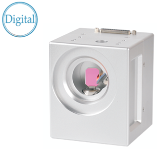
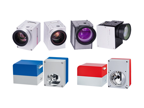
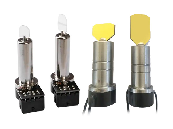
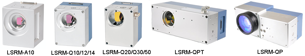
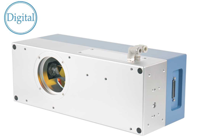
LSRM-A Series is a totally digital 2D galvanometer system. Embedded control system guaranteed the servo loop operation. It is compact, stable and cost-efficient. It is the basic version of LSRM series scanheads. Mirrors of general wavelengths are available, like 1064nm, 532nm 355nm, 10.6um, suitable for laser marking, microscope, drilling, trimming and cutting etc.
| Part number | LSRM-xxxx-10-A10 |
| Aperture | 10mm |
| Beam displacement | 13mm |
| Tracking error time | 220us |
| Offset drift | 50urad/K |
| Gain drift | 75ppm/K |
| Step response time | |
| 1% of full scale | 0.3ms |
| 10% of full scale | 0.8ms |
| Marking speed (1) | 2m/s |
| Positioning speed | 12m/s |
| Writting speed (2) | |
| Good quality | 500cps |
| High quality | 450cps |
| Repeatability | < 22urad |
| Drift over 8 hours (After 30min warm-up) | < 0.3mrad |
| Typical scan angle | 40 degrees |
| Interface (3) | XY2-100 Enhanced |
| Operating temperature | 25°C±10° |
| Power requirements | ±15V DC, 150W |
| Driver mode | Digital |
| Resolution | 16Bit |
| Max laser power (4) | 100W |
| Dimenion | 114x97x94mm |
|
(1) with F-Theta objective, f=160mm (2) single-stroke characters of 1mm height (3) XY2-100 Enhanced with status feedback (4) The mirror of 1064nm can stand max laser power |
|
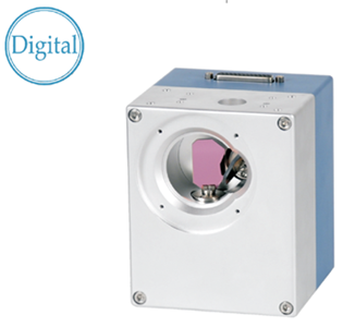
LSRM-Q series is totally digital 2D galvanometer system. System operates based on the embedded platform. It is compact, stable and high quality. More fast and accuracy. The offset drift and gain drift are very low. Mirrors of typical laser wavelengths are available and optimized for inertial and stiffness. Suitable for high end application like ITO scratching, laser micro processing etc.
| LSRM-xxxx-10-Q10 | LSRM-xxxx-12-Q12 | LSRM-xxxx-14-Q14 | |
| Aperture | 10mm | 12mm | 14mm |
| Beam displacement | 13mm | 14.5mm | 18.1mm |
| Tracking error time | 120us | 160us | 160us |
| Weight | 2.05kg | 2.05kg | 2.85kg |
| Offset drift | 30urad/K | 30urad/K | 30urad/K |
| Gain drift | 50ppm/K | 50ppm/K | 50ppm/K |
| Step response time | |||
| 1% of full scale | 0.3ms | 0.3ms | 0.5ms |
| 10% of full scale | 0.8ms | 0.8ms | 1ms |
| Marking speed (1) | 2.5m/s | 2m/s | 2m/s |
| Positioning speed | 15m/s | 11m/s | 8m/s |
| Writting speed (2) | |||
| Good quality | 800cps | 660cps | 660cps |
| High quality | 500cps | 410cps | 410cps |
| Repeatability | < 15urad | < 15urad | < 15urad |
| Drift over 8 hours (After 30min warm-up) | < 0.1mrad | < 0.1mrad | < 0.1mrad |
| Typical scan angle | 40 degrees | 40 degrees | 40 degrees |
| Interface (3) | XY2-100/SL2-100 | XY2-100/SL2-100 | XY2-100/SL2-100 |
| Operating temperature | 25°C±10° | 25°C±10° | 25°C±10° |
| Power requirements | ±15V DC, 150W | ±15V DC, 150W | ±15V DC, 150W |
| Driver mode | Digital | Digital | Digital |
| Resolution | 16Bit | 16Bit | 16Bit |
| Max laser power (4) | 200W | 300W | 400W |
| Dimension | 114x97x94mm | 114x97x94mm | 134x109x107mm |
|
(1) with F-Theta objective, f=160mm (2) single-stroke characters of 1mm height (3) XY2-100-EH with status feedback to change without notice (4) The mirror of 1064nm can stand max laser power,with air cooling |
|||
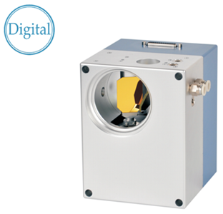
LSRM-Q series is totally digital 2D galvanometer system. System operates based on the embedded platform. It is compact, stable and high quality. More fast and accuracy. The offset drift and gain drift are very low. Mirrors of typical laser wavelengths are available and optimized for inertial and stiffness. Suitable for high end application like ITO scratching, laser micro processing etc. Added water and air cooling function to improve the stability of the system.
(All angles are in optical degrees)
| LSRM-xxxx-20-Q20 | LSRM-xxxx-30-Q30 | LSRM-xxxx-50-Q50 | |
| Aperture | 20mm | 30mm | 50mm |
| Beam displacement | 26.5mm | 36mm | 55mm |
| Tracking error time | 360us | 550us | 1.8ms |
| Weight | 4.9kg | 6.5kg | 7.5kg |
| Offset drift | 30urad/K | 30urad/K | 30urad/K |
| Gain drift | 50ppm/K | 50ppm/K | 50ppm/K |
| Step response time | |||
| 1% of full scale | 0.83ms | 3.04ms | - |
| 10% of full scale | 1.34ms | 6.29ms | - |
| Marking speed | 1m/s | 0.7m/s | 0.3m/s |
| Positioning speed | 6m/s | 3m/s | 1.2m/s |
| Writing speed | |||
| Good quality (1) | 320cps | 220cps | - |
| High quality (2) | 210cps | 150cps | - |
| Repeatability | <15urad | < 15urad | < 15urad |
| Drift over 8 hours (After 30min warm-up) | < 0.1mrad | < 0.1mrad | < 0.1mrad |
| Typical scan angle | 40 degrees | 40 degrees | 40degrees |
| Interface | XY2-100/SL2-100 | XY2-100/SL2-100 | XY2-100/SL2-100 |
| Operating temperature | 25°±10° | 25°±10° | 25°±10° |
| Power requirements | ±15V DC, 150W | ±15V DC, 150W | ±15V DC, 150W |
| Driver mode | Digital | Digital | Digital |
| Resolution | 16Bit | 16Bit | 16Bit |
| Max laser power (3) | 1500W | 3500W | 6000w |
| Dimension | 170x140x130mm | 195x153x150mm | 260x220x170mm |
(1) with F-Theta objective, f=160mm
(2) single-stroke characters of 1mm height
(3) XY2-100-EH with status feedback to change without notice
(4) The mirror of 1064nm can stand max laser power in air cooling
| Part number | Max entrance dia. mm | Control | DC power supply, V |
Dimension LxWxH,mm |
| LSRM-1064-6-QPT | 6 | XY2-100 | 15 | 254x97x105 |
| LSRM-1064-7.2-QPT | 7.2 | XY2-100 | 15 | 254x97x105 |
| LSRM-1064-8.4-QPT | 8.4 | XY2-100 | 15 | 254x97x105 |
| LSRM-532-3.3-QPT | 3.3 | XY2-100 | 15 | 274x109x116 |
| LSRM-532-4-QPT | 4 | XY2-100 | 15 | 274x109x116 |
| LSRM-532-4.6-QPT | 4.6 | XY2-100 | 15 | 274x109x116 |
| LSRM-xxxx-QP20 | XY2-100 | 15 | 350x140x188 | |
| LSRM-xxxx-QP30 | XY2-100 | 15 | 400x155x194 |
(Refer to LSRM-Q datasheets for 2D marking heads)
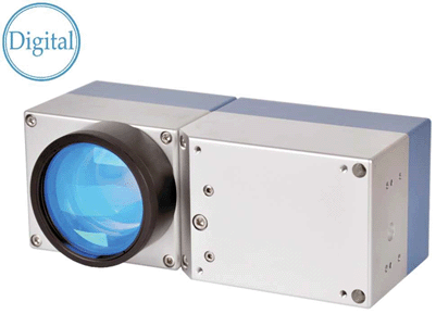
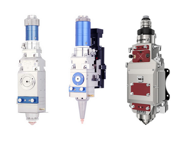
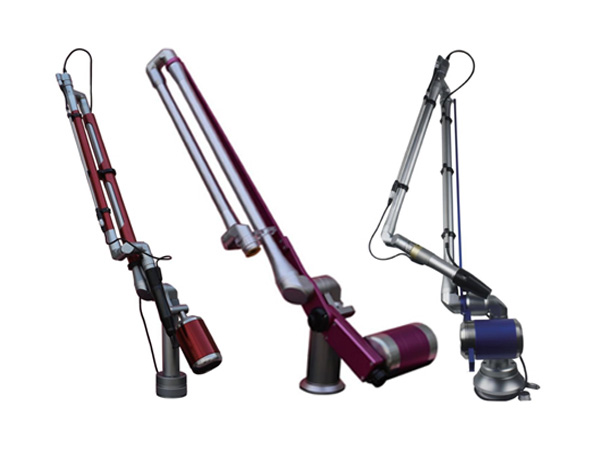
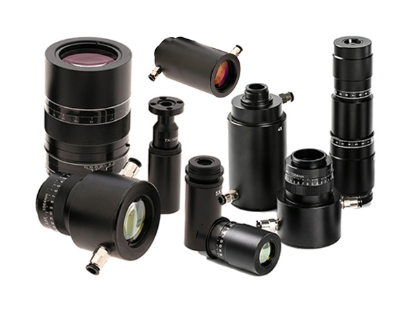
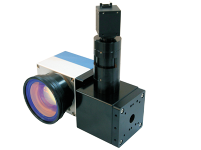
This solution includes a 2D galvoscanner system LSRM-Q Series, a dynamic focusing unit Proton Series, F-theta lens and a galvo system controller LSRM-UMC4. It uses the post-objective scanning technology, the working volume is about 150*150*45 with the FL 210mm F-theta lens. The advantages are fast marking speed, small focal spot and low power loss.
| Laser type | Nd:YAG | Nd:YAG doubled |
| Wavelength | 1064nm | 532nm |
| Beam expansion factor | 1.67 | 3 |
| Input aperture | 6mm/7.2mm/8.4mm | 3.3mm/4mm/4.6mm |
| Scan head apertures | 10/12/14mm | 10/12/14mm |
| Focus range in Z-direction | ±22.5mm (1) | ±2.5mm (2) |
| Tracking error time | 700us | 700us |
| Dimension | 254x97x105mm | 274x109x116mm |
| Remarkds: (1) The focal length of the f-theta lens is 210mm; (2) The focal length of the f-theta lens is 100mm. All the above parameters are theoretical. | ||
(Refer to LSRM-Q10/12/14 datasheet for 2D marking heads)
LSRM-QP series 3D pre-scanning system includes a 2D galvo scanner system LSRM-Q, a dynamic focusing unit Proton series, and a controller LSRM-UMC4. It uses the pre-objective scanning technology to realize the large field and 3D laser application. Their advantages are fast marking speed, small focal spot and low power loss.
| Scanning field | 600x600mm | 800x800mm |
| Focal spot diameter | 364um | 487um |
| Working distance | 502mm | 777mm |
| Resolution | 9um | 12um |
| Scanning field | 400x400mm | 600x600mm | 800x800mm |
| Focal spot diameter | |||
| QP-20 | 34um | 52um | — |
| QP-30 | - | 36um | 48um |
| Working distance | |||
| QP-20 | 502mm | 777mm | — |
| QP-30 | - | 777mm | 1051mm |
| Resolution | 6um | 9um | 12um |
| Scanning field | 400x400mm | 600x600mm |
| Focal spot diameter | 17um | 26um |
| Working distance | 520mm | 795mm |
| Resolution | 6um | 9um |
All of the above parameters are theoretical values.
Distance between edge of deflection unit and working surface. This distance is dependent on the product model and will vary with laser pergence and objective tolerance.
Actual spot size and writing speed are dependent on material and application.
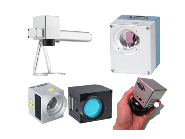
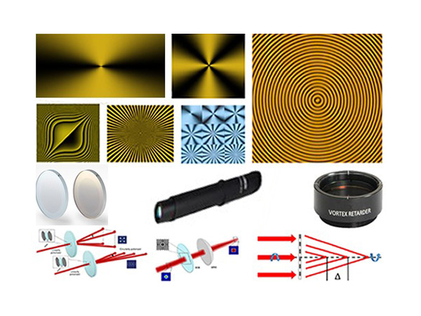
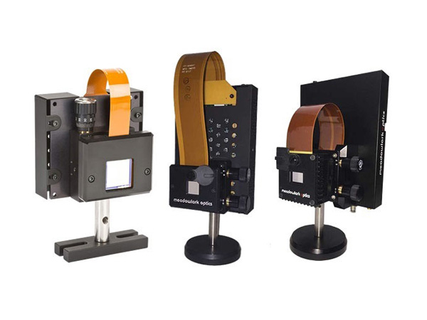
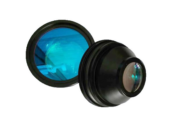
Traditional galvo scanner correction method is given priority to the manual measurement, accuracy is difficult to be guaranteed, thus affecting the processing quality. Galvo scanner with a camera adapter vision module can greatly improve the accuracy of the calibration, and monitor work surfaces at the same time.
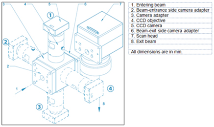
The camera adapter is mounted between the scan head’s beam entrance and the laser flange. (see Fig 1).
Illumination light reflected from the surface of the workpiece pass through achromatic F-theta, galvo scanner, beam splitter, CCD lens to reach the CCD sensor. Adjust beam splitter position to compensate the error of machining and assembly to ensure the optical path of the laser and reflected light coaxial. Make the laser coincides with the CCD image detection point.
Field of view is decided by the lens focal length, CCD camera, CCD camera photosensitive element size together. For example, 160mm lens, CCD target surface size of ½ ", the field of view is 10.4mm * 8.3mm (see table)
| Laser wavelength | 1064nm | 532nm | ||
| Pilot laser wavelength | 635nm | 635nm | ||
| Diameter of entering beam | 14mm | 10mm | ||
| Scan head mirror coating | 1064nm + 635nm | 532nm + 635nm | ||
| Processing field size | 100 x 10 0mm | 100 x 100mm | ||
| Observation wavelength | 1064nm / 635nm | 532nm / 635nm | ||
| Focal length camera objective | 102mm | 102mm | ||
| Flat field objective | 160mm | 210mm | 254mm | 163mm |
| Observation field size | 10.4x8.3mm | 13.7x10.9mm | 16.6x13.3mm | 10.6 x 8.5mm |
Other Parameters:
| Diameter of entering beam | 14mm |
| Operating temperature | 25℃ ±10℃ |
| Max. Chip size | 95 % |
| Camera Connection type | ≥1/2″ |
| Weight(without camera) | C-mount |
| Laser transmissivity | ≈2.6 K g |
| Outline dimension | 115x112x215mm |
Adjust the galvanometer height, find the galvanometer focus position.
Mark the crosshair.
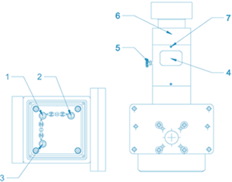
Adjust the focus ring 4 (CW or CCW), to the camera showing a clear image.
Locking screw 5 to lock the focus ring 4.
Loosen screw 7, CW or CCW adjusting ring 6, to make the orientation of the image the same as the crosshairs.
Lock screw 7.
Observe the CCD image crosshair and the marked crosshair position. If the two crosshair does not coincide with each other need to open the protective cover, tuning the knob 2 and knob 3. Take ② (see Figure 1) as an example, when the knob 2 is adjusted, the centre of the image will move left and right diagonally. When the knob 3 is adjusted, the centre of the image will move up and down diagonally .Tuning knob 2 and 3 to make the image crosshair coincide with the marked crosshair.
After tuning restore the cover.
A leading supplier and manufacturer of a wide range of photonics products such as lasers,laser parts & machines.
Office: 10 Bukit Batok Crescent #07-02 The Spire Singapore 658079
Tel: +65 63167112
Fax: +65 63167113
Whatsapp: +65 91904616