 English
 Français
 Deutsch
 euskara
 Русский язык
 Italiano
 Português
 Nederlands
 Polski
 Greek
Greek Lietuva
 Türkçe
 日本語
日本語 한어
한어 中文
中文 தாமில்
 فارسی
فارسی हिंदी
हिंदी Tiếng Việt
 ภาษาไทย
 Pilipino
 Indonesia
 தாமில்

Send us a message
CLOSE


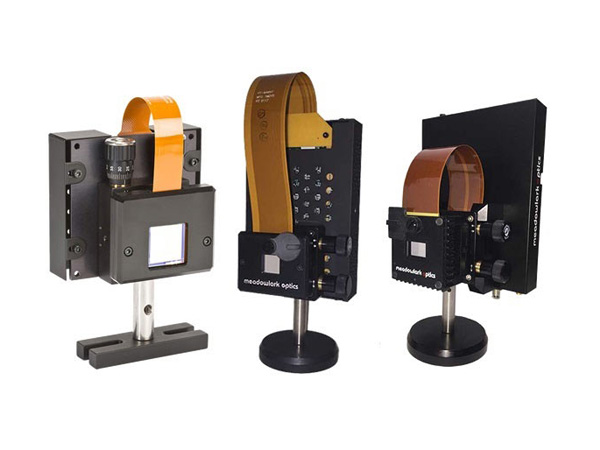

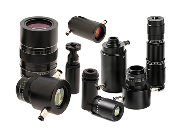


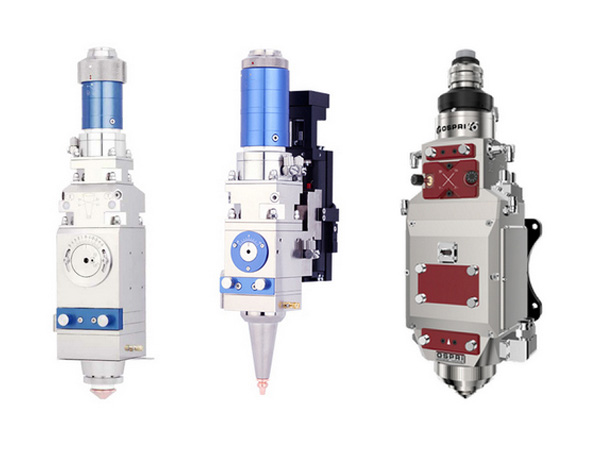
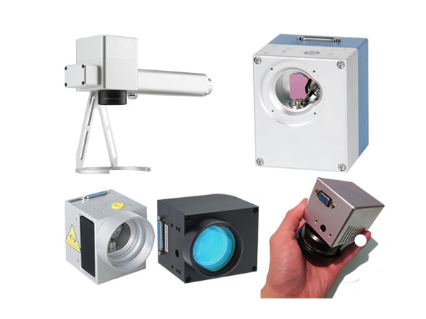
Our marking software has been designed to meet the needs of all types of users of laser marking systems. The software was developed to be a retrofit package for existing systems, or as original software on new systems. The package provides significant advancements over previous laser marking control systems, while remaining extremely user-friendly. It’s an object oriented, graphically interactive, PC control system providing a user the ability define and execute laser marking jobs. Multiple hardware interfaces are supported giving the software the ability to control most Nd:YAG and CO2 laser marking systems.
Unlike some marking software, the operator never has to remember what fonts and logo’s need to be loaded for a particular job. The software automatically performs all required graphic loading. The software does not require users to learn any programming languages or special codes, and yet the software provides all of the flexible, graphic control users are accustomed to, including radial marking, aspect control, character spacing, angular rotations, and full justification. Text to be marked can be fixed or variable. Variable text can be retrieved at runtime from a variety of sources including, the keyboard, a bar code reader, and disk files. Automatic date coding and alphanumeric serialization are included as variable text types. Fonts include laser engraving fonts and Window’s True Type fonts. True Type fonts can be vector filled using user specified density, angle and kerf. Graphics (sometimes called "logo’s" on other systems) can be imported from a large variety of common vector formats. All graphic features are either menu controlled or graphically controlled via the mouse and keyboard.
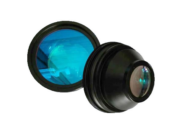
The software can create various objects such as barcode, DataMatrix, text, simple geometrical objects (such as line, rectangle, round-corner rectangle, polygon, circle, ellipse etc), complex graphic objects (such as PLT & BMP files), automatic date coding and alphanumeric serialization.
There are two series of marking cards (interface cards) and relevant software: LMC and STEL. Custom-design is available upon request..
Our marking software has been designed to meet the needs of all types of users of laser marking systems. The software was developed to be a retrofit package for existing systems, or as original software on new systems. The package provides significant advancements over previous laser marking control systems, while remaining extremely user-friendly. It’s an object oriented, graphically interactive, PC control system providing a user the ability define and execute laser marking jobs. Multiple hardware interfaces are supported giving the software the ability to control most Nd:YAG, CO2 and fiber laser marking systems such as adjusting currents, frequency, duty ratio . and red light indication.
Unlike some marking software, the operator never has to remember what fonts and logo’s need to be loaded for a particular job. The software automatically performs all required graphic loading. The softwaredoes not require users to learn any programming languages or special codes, and yet the software provides all of the flexible, graphic control users are accustomed to, including radial marking, aspect control, character spacing, angular rotations, and full justification. Text to be marked can be fixed or variable. Variable text can be retrieved at runtime from a variety of sources including, the keyboard, a bar code reader, and disk files. Automatic date coding and alphanumeric serialization are included as variable text types. Fonts include laser engraving fonts and Window’s True Type fonts. True Type fonts can be vector filled using user specified density, angle and kerf. Graphics (sometimes called "logo’s" on other systems) can be imported from a large variety of common vector formats. All graphic features are either menu controlled or graphically controlled via the mouse and keyboard.
The software can create various objects such as barcode, DataMatrix, text, simple geometrical objects (such as line, rectangle, round-corner rectangle, polygon, circle, ellipse etc), complex graphic objects (such as PLT & BMP files), automatic date coding and alphanumeric serialization.
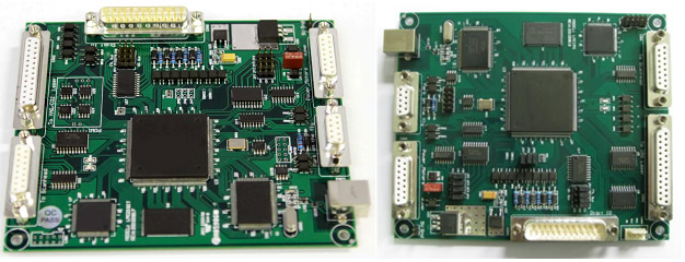
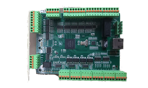
Data transfer:usb2.0 interface
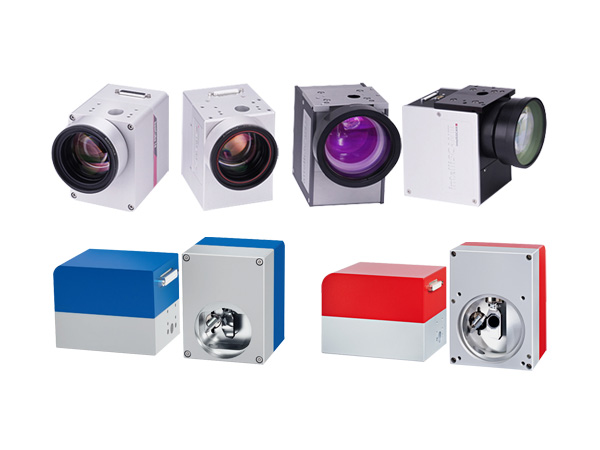
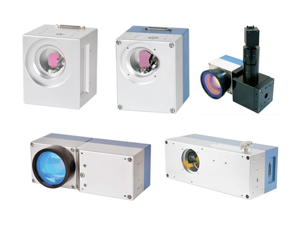
Digital output used for scan head
Support FPK with three ways [optional]
Support high-speed fly marking with rotary encoder
Eight digital input and seven digital output used for other controlled equipment
25 routes general digital signals(TTL compatible), 4 of the IO ports can be OC IO, can connect with relay.
LASER Signal: TTL, used for laser On/Laser Off .
PWM Signal: TTL, used to adjust the frequency and duty ratio.
Tow Direction/Pulse signals, used to control stepping motor.
START Signal: used to connect foot switch
Use 68-pins SCSI 3 socket, connect fiber laser module via 68-pin cable directly
Adjustable digital/analog output used for scan head
Mark-on-fly function with an encoder connected
Extend axes output: Two Direction/pulse signals, used to control stepping motor or servomotor
25 routes general digital signals(TTL compatible), 4 of the IO ports can be OC IO, can connect with relay
Original start signal: Used when marking contents are the same and high speed is required
Compatible with USB2.0
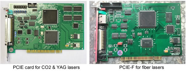
PCIE card (control CO2 and YAG laser) and PCIE-F card (control fiber laser) are also available. Their functions are same as digital cards’s functions.
Dynamic focus .three digital output for scan head
Support FPK with two ways (optional)
6 routes digital input and 6 routes digital output
LASER signal : TTL, used for laser on/laser off
PWM signal: TTL ,used to adjust the frequency and duty ratio
Direction/pulse signals ,used to control stepping motor or servomotor
DB25 connector used for IPG YLP laser directly (optional)
Compatible with USB2.0
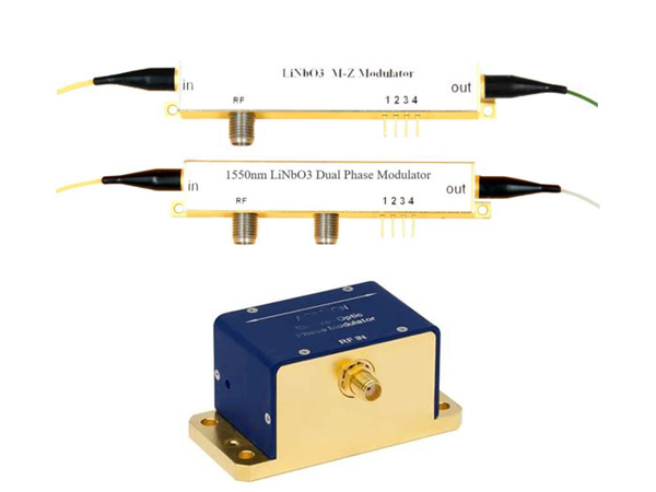
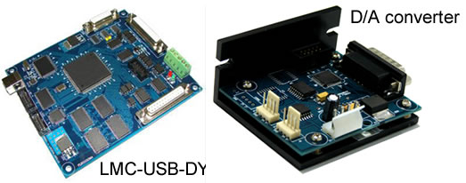
DA converter is an integrated product for digital to analogue single conversion, to enable higher marking accuracy and long distance signal transmission which is less susceptible to electrical noise.
There are two types:
channel: supports 2 channels output, and the digital protocol has not extended coding, which is labeled as “20071012-V101”;
channel: supports 3 channels output, and the digital protocol has the extended coding, which is labeled as "20080107-V103”.
| Software | Type (I/O) | Model | Remarks |
| EzCAD2 (version 2) XP/WIN7/WiN8/WIN10 32/64Bit | USB | LMC-V4-USBFIBER | For fiber lasers. 12 inputs, 8 outputs, 2 extensions, digital galvo |
| LMC-V4-USBDIGI | For CO2/YAG/UV lasers. 16 inputs, 14 outputs, 2 extensions, digital galvo | ||
| LMC-V4-SPI | For SPI lasers, 68-PIN SCSI3. 13 inputs, 8 outputs, 2 extensions, digital galvo | ||
| PCIE | LMC-PEIC-FB | For fiber lasers. DB25, 6 inputs, 2 TTL outputs, 2 extensions, digital galvo | |
| LMC-PEIC-SZ | For CO2/YAG/UV lasers, ON/OFF, PWM, power/frequency, 10 inputs, 8 TTL output, 2 extensions, digital galvo | ||
| Economic & simple | LMC-LMCV4-FIBER-M | For fiber lasers. 2 inputs, 2 TTL outputs, 1 extension, digital galvo | |
| LMC-LMCV4-DIGIT-M | For CO2/YAG/UV lasers, ON/OFF, PWM, power/frequency, 2 inputs, 2 TTL outputs, 1 extension, digital galvo | ||
| LMC-FBLI-B-LV1 | DB25, 2 inputs, 2 TTL outputs, digital galvo | ||
| LMC-FBLI-B-LV4 | DB25, 2 inputs, 2 TTL outputs, digital galvo | ||
| Extensions | LMC-RangeFinding | For measuring distance or fixed distance marking. USB port, 2 inputs + 2 series input, 1 OC output + 2 TTL outputs | |
| LMC-DynamicFocusing | USB port, 8 inputs, 4 TTL/OC outputs, 2 extensions, digital galvo | ||
| LMC-DAboard | XY2-100, 3 analog outputs | ||
| LMC-Rotation | Digital galvo, RS232, 2D/ratary/scan marking | ||
| LMC-Auto-focusing | USB or RS232 | ||
| LMC-Synchronization | 4 inputs, 4 outputs | ||
| EzCAD3 (Version 3) WIN7/WIN8/WIN10, 64BIT | USB | LMC-DLC2 | For all lasers. USB2.0, DB25, XY2-100 (16/18BIT), 4-axis, 10 inputs, 8 outputs |
| LMC-DLC2-M4 | For all lasers. USB2.0, DB25, XY2-100 (16/18BIT), 4-axis, 10 inputs, 8 outputs | ||
| LMC-DLC2-M6 | For all lasers. XY2-100 (16/18BIT), 6-axis, 26 inputs, 24 TTL/OC outputs | ||
| LMC-DLC2-MC | For all lasers. XY2-100 (16/18BIT), SL2-100 (20BIT), 10 inputs, 8 TTL/OC outputs | ||
| LMC-DLC-3D-PRINT | For all lasers. USB2.0, DB25, XY2-100 (16/18BIT), 4-axis, 10 inputs, 8 outputs | ||
| PCIE | LMC-DLC2-PCIE | For fiber laser. USB2.0, DB25, 10 inputs, 8 TTL/OC outputs, XP/WIN7/WIN8/WIN10, 32/64BIT | |
| LMC-DLC2-PCIE-MP4 | DC-3-20PIN, DC3-10PINN-2.54, 4-axis (X,Y,Z,A) | ||
| LMC-DLC2-PCIE-MP6 | 6-axis (XYZABC), 11 inputs, 8 outputs, 2 PWMs, 4 analog inputs, 4 analog outputs | ||
| DLC extensions | LMC-SPI | Converted to SPI laser | |
| LMC-IPG | Converted to IPG-E laser | ||
| LMC-STD | Converted to Co2/YAG laser | ||
| LMC-QCW5V | Converted to QCW IPG-YLM laser | ||
| LMC-QCW24V | Converted to QCW IPG-YLM laser |
A leading supplier and manufacturer of a wide range of photonics products such as lasers,laser parts & machines.
Office: 10 Bukit Batok Crescent #07-02 The Spire Singapore 658079
Tel: +65 63167112
Fax: +65 63167113
Whatsapp: +65 91904616