 English
 Français
 Deutsch
 euskara
 Русский язык
 Italiano
 Português
 Nederlands
 Polski
 Greek
Greek Lietuva
 Türkçe
 日本語
日本語 한어
한어 中文
中文 தாமில்
 فارسی
فارسی हिंदी
हिंदी Tiếng Việt
 ภาษาไทย
 Pilipino
 Indonesia
 தாமில்

Send us a message
CLOSE


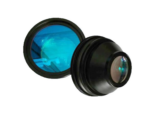


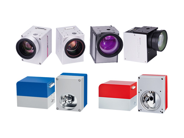
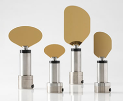
 OSJC series galvanometer scanners are designed by adopting the magnet-moving structure, combining the most advanced international photoelectric sensor technology and the PDM control mode, and using the military-grade processes and technologies.
Adopted the photoelectric sensors which imported from America, and owned the proprietary intellectual property rights.
Differential photoelectric sensor for accurate detection of motor rotor position, good linearity, lower drift, high resolution and repeat positioning.
Accurate load design for 10mm mirrors, high accuracy of motor assembly, reasonable structure, very small static friction coefficient and zero offset, all ensured the best dynamic characteristics for the whole system.
Drives with advanced detection ability of position and speed, greatly improved the dynamic response performance and scanning speed of the whole system.
Design of overload, over-current and reverse connect protection, makes the system running more reliable.
The whole system adopted the optimization Designing of electromagnetic compatibility, with high signal-to-noise ratio and strong anti-interference ability.
This scanner system solved the common problems of motor temperature drift, signal interference and zero drift, etc.
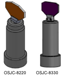
| Part number | OSJC-2203 | OSJC-8330 |
| Speed | ||
| Marking Speed (1), mm/s | 7000 | 1000 |
| Positioning Speed, (1), mm/s | 12000 | 1000 |
| Writing Speed (2), (cps) | 520 | 125 |
| Step Response Time(1% of full scale), us | 285 | 940 |
| Step Response Time(10% of full scale), us | 890 | 1500 |
| Tracking Error Time, us | ≤160 | ≤440 |
| Precision and Error | ||
| Linearity | 99.9% | 99.9% |
| Repeatability (RMS), urad | <8 | <8 |
| Gain Error, mrad | <5 | <5 |
| Zero Offset, mrad | <5 | <5 |
| Long-term Drift Over 8 Hours, mrad | <0.5 | <0.5 |
| Scale Drift, ppm/oC | <40 | <40 |
| Zero Drift, urad/ oC | <15 | <15 |
| Scan Mirror Damage Threshold | ||
| K9 Mirror, J/cm^2 | 9.1 | 9.1 |
| Silicone Mirror, J/cm^2 | 10 | 10 |
| Laser Wavelength (3), nm | 10600/1064/355 | 10600/1064/355 |
| Power and Signal | ||
| Input Voltage, VDC | ±15 | ±15 |
| RMS Current, A | 2 | 2 |
| Interface Signal (Digital) | XY2-100 | XY2-100 |
| Interface Signal (Analog), V | ±5 | ±5 |
| Peak Current, A | 8 | 8 |
| Position Signal Input Resistance, kΩ | 10±1% | 10±1% |
| Machinery Scan Angle (4), o | ±15 | ±15 |
| Working Current, Temperature, Dimension | ||
| Working Temperature, oC | 0--45 | 0--45 |
| Storage Temperature, oC | -10--+60 | -10--+60 |
| Suitable Laser Beam Size, mm | 10 | 30 |
| Galvanometer Scanner Dimension (DXL), mm | D22X35.4+D31X17.6 | D38X81.5+D47X20.5 |
| Galvanometer Scanner Weight, g | 120 | 750 |
Note: The above data are tested after 30 min warm-up.
With F-theta objective, F=160mm, marking 2mm height single character
With F-theta objective, F=160mm, marking 1mm height single character per
second Special wavelength coating film can be customized
If any special requirement, customization is available.
| Working Temperature | 0-45℃ |
| Linearity | 99.9% |
| Setting Time | ≤0.8ms |
| Scale Drift | <40PPM/℃ |
| Zero Drift | <15ΩRad./℃ |
| Long-term Drift Over 8 Hours | <0.5mRad |
| RMS Current | 3.5A |
| Peak Current | 20A(Max) |
| Maximum Scan Angle | ±15° |
| Storage Temperature | -10 to +60℃ |
| Resolution | 12Ωrad |
| Repeatability | 8Ωrad |
| Input Aperture | 20.0mm |
| Beam Displacement | 26mm |
| Motor Weight | 280g |
| Frequency | ≤500Hz |
| Input Voltage | ±24VDC | |
Interface Signal | Digital | XY2-100 |
| Analog | ±5V, ±10V | |
| Analog Signal Input Resistance | 200KΩ±1%(Differential input) | |
| Position Signal Input Resistance | 1KΩ±1% | |
| Position Signal Input Scale Factor | 0.33V/° | |
| Position Signal Output Scale Factor | 0.33V/° | |
| Working Temperature | 0-45℃ | |
| Dimension(DXL) | D28X60+D36X19mm | |
| Part Number | OSJC-1105 | OSJC -1403 | OSJC -2206 |
| Input Aperture | 7mm | 9mm | 10mm |
| Linearity | 99.9% | 99.9% | 99.9% |
| Small Step Response Time | 0.3ms | 0.3ms | 0.35ms |
| Maximum Scan Angle | ±15° | ±15° | ±15° |
| Resolution | 12Ωrad | 12Ωrad | 12Ωrad |
| Repeatability | 8Ωrad | 8Ωrad | 8Ωrad |
| Working Temperature | 0-45℃ | 0-45℃ | 0-45℃ |
| Storage Temperature | -10 to +60℃ | -10 to +60℃ | -10 to +60℃ |
| Input Voltage | ±15VDC | ±15VDC | ±15VDC |
| Interface Signal (Digital) | XY2-100 | XY2-100 | XY2-100 |
| Galvo Weight | 45g | 120g | |
| Drive Board Dimension | 75x50x28mm | 75x50x28mm |
| Part Number | OSJC -7106 | OSJC -7110 | OSJC - 7210 |
| Input Aperture | 10mm | 10mm | 10mm |
| Linearity | 99.9% | 99.9% | 99.9% |
| Small Step Response Time | 0.288ms | 0.5ms | 0.3ms |
| Maximum Scan Angle | ±15° | ±15° | ±15° |
| Resolution | 12Ωrad | 12Ωrad | 12Ωrad |
| Repeatability | 8Ωrad | 8Ωrad | 8Ωrad |
| Working Temperature | 0-45℃ | 0-45℃ | 0-45℃ |
| Storage Temperature | -10 to +60℃ | -10 to +60℃ | -10 to +60℃ |
| Input Voltage | ±15VDC | ±15VDC | ±15VDC |
| Interface Signal (Digital) | XY2-100 | XY2-100 | XY2-100 |
| Galvo Weight | 120g | 120g | 220g |
| Driver Board Dimension | 75x50x28mm | 75x50x28mm | 75×50×28mm |
| Part Number | OSJC -7310 | OSJC -2207 | OSJC -2208 |
| Input Aperture | 10mm | 12mm | 14mm |
| Linearity | 99.9% | 99.9% | 99.9% |
| Small Step Response Time | 0.5ms | 0.45ms | 0.6ms |
| Maximum Scan Angle | ±15° | ±15° | ±15° |
| Resolution | 12Ωrad | 12Ωrad | 12Ωrad |
| Repeatability | 8Ωrad | 8Ωrad | 8Ωrad |
| Working Temperature | 0-45℃ | 0-45℃ | 0-45℃ |
| Storage Temperature | -10 to +60℃ | -10 to +60℃ | -10 to +60℃ |
| Input Voltage | ±15VDC | ±15VDC | ±15VDC |
| Interface Signal (Digital) | XY2-100 | XY2-100 | XY2-100 |
| Galvo Weight | 120g | 130g | |
| Drive Board Dimension | 75x50x28mm | 75x50x28mm |
| Part Number | OSJC -2807 | OSJC -2808 | OSJC - 8220 |
| Input Aperture | 16mm | 20mm | 20mm |
| Linearity | 99.9% | 99.9% | 99.9% |
| Small Step Response Time | 1ms | 1.2ms | 0.8ms |
| Maximum Scan Angle | ±15° | ±15° | ±15° |
| Resolution | 12Ωrad | 12Ωrad | 12Ωrad |
| Repeatability | 8Ωrad | 8Ωrad | 8Ωrad |
| Working Temperature | 0-45℃ | 0-45℃ | 0-45℃ |
| Storage Temperature | -10 to +60℃ | -10 to +60℃ | -10 to +60℃ |
| Input Voltage | ±24VDC | ±24VDC | ±24VDC |
| Interface Signal (Digital) | XY2-100 | XY2-100 | XY2-100 |
| Galvo Weight | 280g | 280g | 280g |
| Drive Board Dimension | 90×64×34mm | 90×64×34mm | 80×54×33mm |
| Part Number | OSJC -3808 | OSJC -8330 | OSJC -8250 |
| Input Aperture | 30mm | 30mm | 50mm |
| Linearity | 99.9% | 99.9% | 99.9% |
| Small Step Response Time | 1.6ms | 1.2ms | 2.5ms |
| Maximum Scan Angle | ±15° | ±15° | ±15° |
| Resolution | 12Ωrad | 12Ωrad | 12Ωrad |
| Repeatability | 8Ωrad | 8Ωrad | 8Ωrad |
| Working Temperature | 0-45℃ | 0-45℃ | 0-45℃ |
| Storage Temperature | -10 to +60℃ | -10 to +60℃ | -10 to +60℃ |
| Input Voltage | ±24VDC | ±24VDC | ±24VDC |
| Interface Signal (Digital) | XY2-100 | XY2-100 | XY2-100 |
| Galvo Weight | 750g | ||
| Drive Board Dimension | 90×64×34mm |
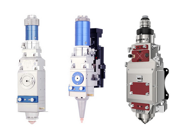
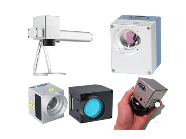
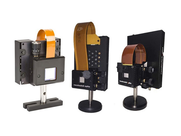
The galvanometer system is a high-precision and high-speed servo control system composed of a driving board, galvo and scan mirror, mainly used for laser marking, laser engraving, stage lighting control, etc.
The working principle of this system is that by inputting a position signal, the oscillating motor (galvanometer) will swing a certain angle according to a certain voltage and angle conversion ratio. The entire process adopts closed-loop feedback control, which is jointly operated by five control circuits/parts: position sensor, error amplifier, power amplifier, position discriminator, and current integrator.
The OSST series galvanometer systems produced by our company utilize the latest generation of integrated circuits and adopts various anti-interference methods to drive the circuit board. The system not only has strong anti-interference ability, high reliability, good linearity, high repetition accuracy, short response time, but also has a small size, which is easy to install and transport.
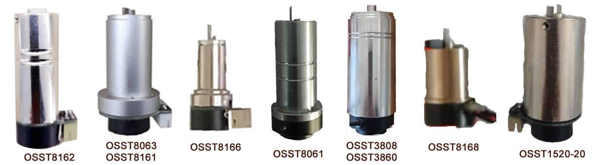
| Part number | OSST8162 | OSST8161 | OSST8063 |
| Optical apertures supported, two-axis | ≦8mm beam | ≦10mm beam | ≦12mm beam |
| Small-step response time | 0.2ms@5mm beam | 0.3ms@10mm beam | 0.6ms@12mm beam |
| Max mechanical rotation angle | ±20°-30 ° | ±20° | ±20° |
| Linearity | 99.9% @±20° | 99.9%@±20° | 99.9%@±20° |
| Peak current | 5A | 5A | 10A |
| Coil resistance | 3Ω±10% | 1.8Ω±10% | 2Ω±10% |
| Coil inductance | 180μH ±10% | 280μH ±10% | 260μH ±10% |
| Operation temp | 0℃-40℃ | 0℃-40℃ | 0℃-40℃ |
| Operation temp. (option) | -40—﹢85 | -40—﹢85 | -40—﹢85 |
| Weight | 80g | 105g | 180g |
| Rotor inertia | 0.125g·cm2 | 0.34g·cm2 | 1.2g·cm2 |
| Torque constant | 5.1N·mm/A | 7.3N·mm/A | 12 N·mm/A |
| Max. RMS current | 2.1A | 2.5 5A | 3.52A |
| Weight with cable | 72g | 263 g | 340g |
| Connector | C3030F-2*4 | C3030F-2*4 | C3030F-2*4 |
| Loading inertia | 0.1 g·cm2—0.54 g·cm2 | 0.3 g·cm2—1.52 g·cm2 | 1.0 g·cm2—6 g·cm2 |
| Following error | 0.11 ms | 0.142ms | 0.22 ms |
| Dimension | D15x31+D15.4x11mm | D22X36+D31x8.6+D21x9mm | D22x36+D31x8.6+D21x9mm |
| Mirror thickness | 2.1mm | 2.1mm | 2.1mm |
| Application | Stage lighting, laser animation | Ultra high speed flying marking, ultra high speed online rapid marking | Ultra high-speed flying marking, ultra high-speed online rapid marking metal, non-metallic precision laser marking, laser rapid prototyping, laser resistance adjustment and laser radar, etc |
| Part number | OSST8166 | OSST8168 | OSST8061 |
| Optical apertures supported, two-axis | 1-6mm beam | 1-10mm beam | 20-25mm beam |
| Small-step response time | 0.3ms@5mm beam | 0.3ms@5mm beam | 0.7ms@20mm beam |
| Max mechanical rotation angle | ±20° | ±20° | ±20° |
| Linearity | 99.9%@ ±20° | 99.9%@±20° | 99.9%@ ±20° |
| Peak current | 1.5A | 1.5A | 6A |
| Coil resistance | 2.3Ω±10% | 2.3Ω±10% | 2.1Ω±10% |
| Coil inductance | 420μH ±10% | 420μH ±10% | 360μH ±10% |
| Operation temp | 0℃-40℃ | 0℃-40℃ | 0℃-40℃ |
| Operation temp. (option) | -40—﹢85 | -40—﹢85 | -40—﹢85 |
| Weight | 26g | 26g | 210g |
| Rotor inertia | 0.028g·cm | 2.25N·mm/A | 5.1g·cm2 |
| Torque constant | 2.25N·mm/A | 2.25N·mm/A | 22N·mm/A |
| Max. RMS current | 1.8A | 1.8A | 5A |
| Weight with cable | 49 g | 425 g | |
| Connector | C3030F-2*4 | PHD2*4 | C3030F-2*4 |
| Loading inertia | 0.02 g·cm2—0.05 g·cm2 | 0.02 g·cm2—0.05 g·cm2 | 8 g·cm2—24 g·cm2 |
| Following error | 0.11 ms | 0.15 ms | 0.35 ms |
| Dimension | D10x16+D13x3+D15x10.5mm | D15X8+D14x15 | D28x58+D36x15+D25x5mm |
| Mirror thickness | 1.0mm | 1.mm | 3.0mm |
| Application | High speed online flying marking, high-speed high-precision static marking, etc | High speed online flying marking, high-speed high-precision static marking, etc | Precision laser marking, laser rapid prototyping, laser resistance modulation, laser radar, etc |
| Part number | OSST3808 | OSST3860 |
| Optical apertures supported, two-axis | 25-50mm beam | 30-60mm beam |
| Small-step response time | 1.2ms@25mm beam | 1.3ms@30mm beam |
| Max mechanical rotation angle | ±20° | ±20° |
| Linearity | 99.9%@±20° | 99.9%@±20° |
| Peak current | 7.6A | 9.6A |
| Coil resistance | 2Ω±10% | 2Ω±10% |
| Coil inductance | 260μH ±10% | 260μH ±10% |
| Operation temp | 0℃-40℃ | 0℃-40℃ |
| Operation temp. (option) | -40—﹢85 | -40—﹢85 |
| Weight | 520g | 520g |
| Rotor inertia | 6.25g·cm2 | 8.2g·cm2 |
| Torque constant | 28N·mm/A | 31·mm/A |
| Max. RMS current | 6.3 A | 12A |
| Weight with cable | 520G | 520G |
| Connector | C3030F-2*4 | C3030F-2*4 |
| Loading inertia | 12g·cm2—24 g·cm2 | 12g·cm2—35 g·cm2 |
| Following error | 0.28 ms | 0.35 ms |
| Dimension | D38X76+D36x5+D25x5mm | D38x76+D35x5+D25x5mm |
| Mount dia. Of the mirror | 7mm | 7mm |
| Application | Precision laser marking, laser rapid prototyping, laser resistance modulation, laser radar, etc | Precision laser marking, laser rapid prototyping, laser resistance modulation, laser radar, etc |
| Part number | OSST1520-20 | OSST1520-15 |
| Optical apertures supported, two-axis | ≦10mm beam | ≦10mm beam |
| Small-step response time | 0.3ms@10mm beam | 0.3ms@10mm beam |
| Max mechanical rotation angle | ±20° | ±20° |
| Linearity | 99.9%@±20° | 99.9%@±20° |
| Peak current | 5A | 5A |
| Coil resistance | 1.62Ω±10% | 1.8Ω±10% |
| Coil inductance | 103μH ±10% | 280μH ±10% |
| Operation temp | 0℃-40℃ | 0℃-40℃ |
| Operation temp. (option) | -40—﹢85 | ---- |
| Weight | 105g | 33g |
| Rotor inertia | 0.34g·cm2 | 0.34g·cm2 |
| Torque constant | 7.5N·mm/A | 7.5N·mm/A |
| Max. RMS current | 2.5 A | 2.5 A |
| Weight with cable | 263 g | Socket |
| Connector | PHD2*4 | PHD2*4 |
| Loading inertia | 0.35 —1.5 g·cm2 | 0.35 —1.5 g·cm2 |
| Following error | 0.15 ms | 0.15 ms |
| Dimension | D20X26+D15x11mm/37mm | D15X26+D15x11mm/37mm |
| Mirror thickness | 2.0mm (to be stuck) | 2.0mm (to be stuck) |
| Application | Ultra high speed flying marking, ultra high speed online rapid marking | Ultra high speed flying marking, ultra high speed online rapid marking |
Remarks:
All the galvos are chrome coated cover.
The scan mirrors at the laser wavelengths of 1064nm, 532nm, 355nm, 266nm, 10.6um and others are available upon request.
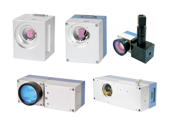
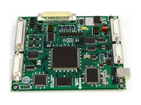
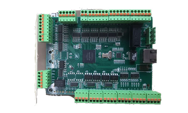
There are 2 types of drive boards for OSST series galvos: one board to drive 2 galvos (1-to-2 board or just called board, default); one board to drive 1 galvo (1-to-1 board). Their driving capabilities and main performance are same. The main difference is the dimension.
General specifications:
Supply power: ±15VDC to ±24VDC
Analog input position signal: ±5V (default), ±10V available upon requestion.
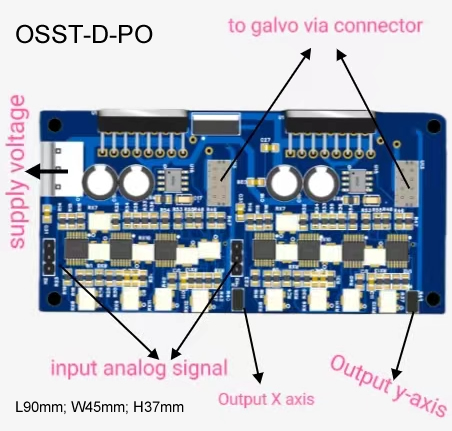
Position signal output (option): 1:1 port and 1:10 port.
1. 1-to-2 Boards
1.1 1-to-2 Board without Position Output Signal (OSST-D)
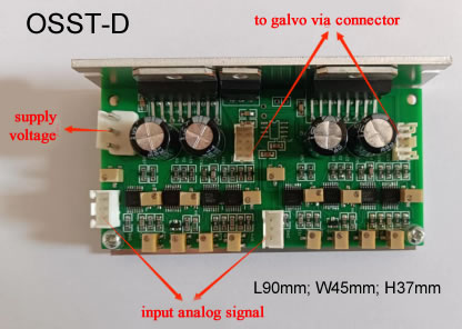
This driver is mostly used in 2D laser marking/scanning.
1.2 1-to-2 Board with Position Signal Output (OSST-D-PO)
2. 1-to-1 Boards
1-to-2 Board with Position Signal Output (OSST-D-1-PO)
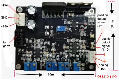
There are 2 position signal outputs for use.
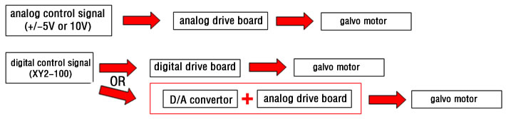
Depending the required control signal of the drive boards and the control signal of your control system, a D/A card may be needed.
Our broad range of closed loop galvanometer-based optical scanning components and systems offer the systems integrator the maximum galvanometer-based performance for any positioning or scanning requirement. Our superior positioning performance comes from advanced actuator designs, innovative patented position detection techniques, the consistency of our high quality manufacturing process and our continued commitment to advancing the state of galvo technology. With our extensive range of scanning options, application expertise and world-wide technical support, we are ready to be your partner in scientific and OEM optical system applications.
Just as important as our superior positioning system performance is the product reliability, lifetime and support that you need for long term system and market success. Superior product lifetime and reliability result from disciplined design technique and simulation, the best in bearing and component technology and quality manufacturing processes and workmanship. We take great pride in the performance and the extensive lifetime of our products. These high standards in our manufacturing processes guarantee the performance consistency that you need to design the high calibre systems demanded in today’s competitive marketplace.
We offer a complete range of closed loop galvanometers, servo drivers and system options for the maximum in price/performance options, system design flexibility and ease of integration.
Proprietary Moving Magnet Actuator Technology for the highest positioning speed.
Proprietary Moving Coil Actuator Technology for the highest positioning accuracy.
Patented Capacitive Position Detector Technology for the highest positioning accuracy and stability
Patented Optical Position Detector Technology offers positioning accuracy at lower cost.
Product Consistency and Reliability for extended system lifetimes and uptime.
A Broad Range of Products sized for optimum performance for apertures from 1mm to 50mms.
These galvo technologies are offered in three families of optical scanning products.
The Moving Magnet Scanners with Advanced Optical Position Detector (62xxH series such as 6200H, 6210H, 6215H, 6220H, 6230H, 6231H, 6240H, 6250H, 6260H, and 83xxK series such as 8300K, 8310K, 8315K, 8320K, 8330K, 8331K, 8340K, 8350K, 8360K )
The Moving Magnet Scanners with Capacitive Position Detector (Model 6860, 6870, 6880)
The Moving Coil Scanners with Capacitive Position Detector (Model 6350, 6450, 6650, 6900, 6400)
The key Servo Driver Technologies and offerings include:
Surface Mount Technology (SMT) driver boards for compact system size.
Proprietary Class 1 Integrating Servo Drivers for the highest positioning accuracy and stability.
Proprietary Class 0 Non-Integrating Servo Drivers for the highest speed and lowest cost.
System Control and Interface Features for ease of system integration.
These servo technologies are offered in analog and digital versions. The analog drivers include 670, 671, 672, 673, 677 series and the digital drivers include DC900, DC2000, and D3000 plus.
For more complete levels of system integration and solutions, we also provide the following system components and solutions:
Standard Two Axis X/Y Mounts and Mirrors Sets from 3mm to 50mm apertures (called marking heads, laser scanners).
Standard and Custom Mirrors for all galvos.
Standard and Custom Interface Cables.
PositionProtm PC-based Hardware and Software Galvo Control.
The combination of our Moving Magnet Actuator technology and our innovative patented Advanced Optical Position Detector design offers the highest positioning speed and excellent accuracy in the smallest, lower cost closed loop galvanometers. Scanning system applications can be designed and optimized for speed, size, cost and accuracy with typical beam diameters in the 1 to 3mm range.
The Moving Magnet Scanner's Positioning Speed comes from advanced galvanometer and actuator design for the highest system resonant frequency and RMS power capability. The higher resonant frequency of our moving magnet actuator design, the intense magnetic field strength of state of the art neodymium-iron-boron magnets and our advanced servo driver options allow superior system bandwidths, step response times and repetition rates with excellent wobble and jitter performance.
Our newly patented advanced optical position detector design coupled with the positioning precision of the moving magnet actuator provides excellent repeatability and accuracy . The advanced optical position detector is designed to provide high positioning linearity, repeatability and stability over time and temperature, and lower closed loop galvo cost in the smallest, most compact package.
Superior product lifetime and reliability result from disciplined design technique, the best in bearing technology and quality manufacturing processes and workmanship. We take great pride in the performance of our products. Our scanner designs are computer modelled and have been life-test proven to billions of cycles of operation. Our high standards of manufacturing quality guarantees the performance consistency that you need to design the high quality systems demanded in today's competitive marketplace.
Our popular 62xxH Series of closed loop, galvanometer-based scanners is consistently the industry’s leading solution for high-performance laser beam steering. Each motor combines our moving magnet actuator technology with a position detector only available from Cambridge Technology. This patented technology features stable positioning while achieving the fastest scan speeds available in its category. Whether your focus is on speed, accuracy, or footprint, the 62xxH Series delivers both performance and value.
Attain high-performance and reliability for your value-driven application:
Industry’s fastest motor speeds deliver maximum throughput with long-term reliability
High-accuracy output across a diverse range of application scanning needs
Robust design supports consistent stability over long product lifetimes
Footprint of compact models ensures ease of integration for small spaces
Available with a wide range of mirrors sizes (3 to 50 mm) and coating options
| Part number | 6200H | 6210H | 6215H | 6220H |
| Recommended Aperture Size (mm) | 3 to 7 | 3 to 7 | 3 to 7 | 5 to 10 |
| Wavelength Options | 355 nm / 532 nm / 1030 nm - 1080 nm / 9.4 Ωm - 10.6 Ωm Broadband Coatings: 350 nm – 12 Ωm | |||
| Maximum Scan Angle (degrees) | 40° | 40° | 40° | 40° |
| Rotor Inertia (gm·cm2, ±10%) | 0.013 | 0.018 | 0.028 | 0.125 |
| Torque Constant (dyne·cm/amp, ±10%) | 1.20x10⁴ | 2.79x10⁴ | 3.78x10⁴ | 6.17x10⁴ |
| Maximum Rotor Temperature (°C) | 110° | 110° | 110° | 110° |
| Thermal Resistance (Rotor to Case) (°C/watt, max) | 3.8 | 2.0 | 1.0 | 1.0 |
| Coil Resistance (ohms, ±10%) | 2.14 | 3.7 | 2.5 | 2.79 |
| Coil Inductance (ΩH, ±10%) | 52 | 109 | 94 | 180 |
| Back EMF Voltage (ΩV/°/sec, ±10%) | 20.9 | 48.7 | 66 | 108 |
| RMS Current (A at Tcase = 50°C, maximum) | 2.3 | 2.4 | 4.1 | 3.9 |
| Peak Current (A, maximum) | 6 | 8 | 20 | 20 |
| Small Angle Step Response1 (typical) | 3 mm Y mirror 130 Ωs | 3 mm Y mirror 100 Ω | 3 mm Y mirror 200 Ω | 5 mm Y mirror 250 Ω |
| Weight (grams, typical) | 13.3 | 18 | 25.8 | 42.5 |
| Dimension (mm) | 12.7x29 | 12.7x37.3 | 12.7x53.8 | 15.3x52 |
| Part number | 6230H | 6231H | 6240H | 6250H | 6260H |
| Recommended Aperture Size (mm) | 8 to 15 | 8 to 15 | 12 to 25 | 25 to 75 | 30 to 100 |
| Wavelength Options | 355 nm / 532 nm / 1030 nm - 1080 nm / 9.4 Ωm - 10.6 Ωm Broadband Coatings: 350 nm – 12 Ωm | ||||
| Maximum Scan Angle (degrees) | 40° | 40° | 40° | 40° | 40° |
| Rotor Inertia (gm·cm2, ±10%) | 0.97 | 0.82 | 2.4 | 15.6 | 47.5 |
| Torque Constant (dyne·cm/amp, ±10%) | 1.31x10⁵ | 1.11x10⁵ | 2.0x10⁵ | 7.08x10⁵ | 8.5x10⁵ |
| Maximum Rotor Temperature (°C) | 110 | 110 | 110 | 110 | 110 |
| Thermal Resistance (Rotor to Case) (°C/watt, max) | 0.8 | 1.0 | 0.62 | 0.35 | 0.2 |
| Coil Resistance (ohms, ±10%) | 1.07 | 1.27 | 1.03 | 1.69 | 0.60 |
| Coil Inductance (ΩH, ±10%) | 173 | 176 | 350 | 1030 | 530 |
| Back EMF Voltage (ΩV/°/sec, ±10%) | 229 | 195 | 346 | 1220 | 1480 |
| RMS Current (A at Tcase = 50°C, maximum) | 7.1 | 5.8 | 8.2 | 7.1 | 12 |
| Peak Current (A, maximum) | 25 | 25 | 25 | 20 | 40 |
| Small Angle Step Response1 (typical) | 10mm mirror 250us | 10mm Y mirror 250us | 15mm Y mirror 350us | 50 mm Y mirror 3ms | 50 mm Y mirror 2.1ms |
| Weight (grams, typical) | 267 | 142 | 356 | 590 | 1200 |
| Dimension (mm) | 33x70 | 33x68.2 | 33x86.5 | 40.6x113.4 | 40.6x159.9 |
Position Detector (specifications common across all models):
| Linearity | 99.9% minimu m, over 20°; 99.5% typical, over 40° |
| Scale Drift | 50 ppm/°C, maximum |
| Zero Drift | 15 Ωrad/°C, maximum |
| Repeatability, Short-Term | 8 Ωrad |
| Output Signal, Common Mode | 155 ΩA minimum, with AGC current of 30 mA |
| Output Signal, Differential Mode | 12 ΩA/° (±2.5%) at common mode current of 155 ΩA |
| Output Signal, Common Mode to Differential Mode Ratio | 12.5 (±2.5%) |
Supports apertures of 3mm, 4mm, 5mm, 6mm, and 7mm. Shown here with A connecter and 3mm Y mirror.All Position Detector specifications apply with our servo driver after a 30 second warm-up. All angles are in mechanical degrees. Consult manual for complete operating instructions.
Mechanical
| Rated Angular Excursion: | 40° |
| Rotor Inertia: | 0.018 gm cm2 , +/-10% |
| Torque Constant: | 2.79x10⁴ dyne cm/amp, +/-10% |
| Maximum Rotor Temperature: | 110° C |
| Thermal Resistance (Coil to Case): | 2° C/Watt, Max |
Electrical/Drive Mechanism
| Coil Resistance: | 3.72 Ohms, +/-10% |
| Coil Inductance: | 109 µH, +/-10% |
| Back EMF Voltage: | 48.7 µV/degree/sec, +/-10% |
| RMS Current: | 2.4 Amperes at Tcase of 50° C, Max |
| Peak Current: | 8 Amperes, Max |
| Small Angle Step Response Time: | 100 µs, with 3mm, Y mirror, settled to 99% |
Position Detector
| Linearity: | 99.9 %, Minimum, over 20 degrees, 99.5% Typical, over 40 degrees |
| Scale Drift: | 50 PPM/° C, Maximum |
| Zero Drift: | 15 µrad/° C, Maximum |
| Repeatability, Short Term: | 8 microradians |
| Output Signal, Common Mode: | 155 µA with AGC current of 30mA, +/-20% |
| Output Signal, Differential Mode: | 12 µA/°, at common mode current of 155 µA, +/-20% |
The 6230H galvanometer can be designed and optimized for speed, size, cost and accuracy with typical beam diameters of 8mm, 10mm, 12mm, and 15mm. It is shown here with a 10mm Y mirror. All Position Detector specifications apply with our servo driver after a 30 second warm-up. All angles are in mechanical degrees. Consult manual for complete operating instructions.
Mechanical Specifications
| Rated Angular Excursion: | 40° |
| Rotor Inertia: | 0.97 gm cm2, +/-10% |
| Torque Constant: | 1.31x10⁵ dyne cm/amp, +/-10% |
| Maximum Rotor Temperature: | 110°C Thermal |
| Resistance (Rotor to Case): | 0.80°C/Watt, Max |
Electrical Specifications/Drive Mechanism
| Coil Resistance: | 1.07 Ohms, +/-10% |
| Coil Inductance: | 173 uH, +/-10% |
| Back EMF Voltage: | 229 µV/degree/sec, +/-10% |
| RMS Current: | 7.1 Amperes at Tcase of 50°C, Max |
| Peak Current: | 25 Amperes, Max |
| Small Angle Step Response Time: | 250 µs, with 8mm Y Mirror, settled to 99% 250 µs, with 10mm Y mirror, settled to 99% |
Position Detector
| Linearity: | 99.9 %, Minimum, over 20 degrees, 99.5% Typical, over 40 degrees |
| Scale Drift: | 50 PPM/°C, Maximum |
| Zero Drift: | 15 µrad/°C, Maximum |
| Repeatability, Short Term: | 8 microradians |
| Output Signal, Common Mode: | 155 µA with AGC current of 30mA, +/-20% |
| Output Signal, Differential Mode: | 11.7 µA/°, at common mode current of 155 µA, +/-20% |
6230HM50A MiniCT split cable 671XX connectors with 12” cable, ±25 optical degrees. Mxx denotes maximum optical degrees.
6230HB with 67723H will work
6230H with 67123H & adaptor cable 6010-20-xxx will work.
6230HA with 671 will work.
Remark: if the connectors of the galvo and drive board are not matched, an adaptor cable is needed to make them matched. For example, an adaptor cable is needed if you want to use 6230HB with 67123H.
The 6231H supports apertures of 8mm, 10mm, 12mm, and 15mm. It is shown here with the C connector and a 10mm Y mirror. All Position Detector specifications apply with our servo driver after a 30 second warm-up. All angles are in mechanical degrees. Consult manual for complete operating instructions.
Mechanical
| Rated Angular Excursion: | 40° |
| Rotor Inertia: | 0.82 gm cm2 , +/-10% |
| Torque Constant: | 1.11x10⁵ dyne cm/amp, +/-10% |
| Maximum Rotor Temperature: | 110° C |
| Thermal Resistance (Rotor to Case): | 1° C/Watt, Max |
Electrical/Drive Mechanism
| Coil Resistance: | 1.27 Ohms, +/-10% |
| Coil Inductance: | 176 µH, +/-10% |
| Back EMF Voltage: | 195 µV/degree/sec, +/-10% |
| RMS Current: | 5.8 Amperes at Tcase of 50° C, Max |
| Peak Current: | 25 Amperes, Max |
| Small Angle Step Response Time: | 250 µs, with balanced load of 0.3 gm*cm2 |
Position Detector
| Linearity: | 99.9 %, Minimum, over 20 degrees, 99.5% Typical, over 40 degrees |
| Scale Drift: | 50 PPM/° C, Maximum |
| Zero Drift: | 15 µrad/° C, Maximum |
| Repeatability, Short Term: | 8 microradians |
| Output Signal, Common Mode: | 155 µA with AGC current of 30mA, +/-20% |
| Output Signal, Differential Mode: | 11.7 µA/°, at common mode current of 155 µA, +/-20% |
| Mechanical Specifications | ||
| Optical Aperture, Two-Axis, Std | 8, 10 & 12 | mm |
| Rated Angular Excursion | 40 | º |
| Rotor Inertia | 0.82 | gm*cm2, +/ - 10% |
| Torque Constant | 11,100 | dyne-cm/amp, +/ - 10% |
| Maximum Coil Temperature | 110 | ºC |
| Thermal Resistance (Coil to Case) | 1.0 | ºC/Watt, Max |
| Electrical Specifications Drive Mechanism | ||
| Coil Resistance | 1.27 | Ohms, +/- 10% |
| Coil Inductance | 176 | ΩH, +/- 10% |
| Back EMF voltage | 195 | mV/degree/sec, +/- 10% |
| RMS Current | 5.8 | Amperes at Tcase of 50ºC, Max |
| Peak Current | 25 | Amperes, Max |
| Small Angle Step Response Time | 0.25 | ms, with balanced load of 0.3 gm*cm2 |
| Position Detector | ||
| Linearity | 99.99 | Minimum, over 20 degrees |
| Scale Drift | 50 | PPM/ºC, Maximum |
| Zero Drift | 15 | Ωrad/º C, Maximum |
| Repeatability, Short Term | 8 | microradians |
| Output Signal, Common Mode | 155 | ΩA with AGC current of 30 mA, +/-20% |
| Output Signal, Differential Mode | 11.7 | ΩA/º, at common mode current of 155 ΩA, +/-20% |
| Driver | 67723 | |
The 6240H galvanometer can be designed and optimized for speed, size, cost and accuracy with typical beam diameters of 12mm, 15mm, 20mm, 25mm, and 30mm. It is shown here with a 12mm Y mirror. All Position Detector specifications apply with our servo driver after a 30 second warm-up. All angles are in mechanical degree. Consult manual for complete operating instructions.
Mechanical Specifications
| Rated Angular Excursion: | 40° |
| Rotor Inertia: | 2.4 gm cm2, +/-10% |
| Torque Constant: | 2.0x10⁵ dyne cm/amp, +/-10% |
| Maximum Coil Temperature: | 110°C |
| Thermal Resistance (Coil to Case): | 0.62°C/Watt, Max |
Electrical Specifications/Drive Mechanism
| Coil Resistance: | 1.03 Ohms, +/-10% |
| Coil Inductance: | 350µH, +/-10% |
| Back EMF Voltage: | 346 µV/degree/sec, +/-10% |
| RMS Current: | 8.2 Amperes at Tcase of 50°C, Max |
| Peak Current: | 25 Amperes, Max |
| Small Angle Step Response Time: | 300 µs, with 12mm Y mirror, settled to 99% 350µs, with 15mm Y mirror, settled to 99% 650 µs, with 20mm Y mirror, settled to 99% |
Position Detector
| Linearity: | 99.9 %, Minimum, over 20 degrees, 99.5% Typical, over 40 degrees |
| Scale Drift: | 50 PPM/°C, Maximum |
| Zero Drift: | 15 µrad/°C, maximum |
| Repeatability, Short Term: | 8 microradians |
| Output Signal, Common Mode: | 155 µA with AGC current of 30mA, +/-20% |
| Output Signal, Differential Mode: | 11.7 µA/°, at common mode current of 155 µA, +/-20% |
Our 83xxK Series of scanners builds on the 62xxH Series’ speed and reliability with even higher resolution and thermal stability for the most demanding, high-precision applications. Each model includes our best-in-class, moving magnet actuator technology and enhanced position detector only available from Cambridge Technology. With its lower drift and noise, the 83xxK Series is ideal for applications requiring precise features such as micromachining and large field applications that are dependent on stability.
Achieve the highest level of scanning accuracy, speed, and reliability:
Industry’s fastest motor speeds, with even higher resolution and stability
Superior precision and accuracy that ensures high-quality processing output
Robust design supports consistent reliability over long product lifetimes
Footprint of compact models ensures easy system integration for small spaces
Available with a wide range of mirror sizes (3 to 50 mm) and coating options
| Part number | 8300H | 8310H | 8315H | 8320H |
| Recommended Aperture Size (mm) | 3 to 7 | 3 to 7 | 3 to 7 | 5 to 10 |
| Wavelength Options | 355 nm / 532 nm / 1030 nm - 1080 nm / 9.4 Ωm - 10.6 Ωm Broadband Coatings: 350 nm – 12 Ωm | |||
| Maximum Scan Angle (degrees) | 40° | 40° | 40° | 40° |
| Rotor Inertia (gm·cm2, ±10%) | 0.013 | 0.018 | 0.028 | 0.125 |
| Torque Constant (dyne·cm/amp, ±10%) | 1.20x10⁴ | 2.79x10⁴ | 3.78x10⁴ | 6.17x10⁴ |
| Maximum Rotor Temperature (°C) | 110° | 110° | 110° | 110° |
| Thermal Resistance (Rotor to Case) (°C/watt, max) | 3.8 | 2.0 | 1.0 | 1.0 |
| Coil Resistance (ohms, ±10%) | 2.14 | 3.7 | 2.5 | 2.79 |
| Coil Inductance (ΩH, ±10%) | 52 | 109 | 94 | 180 |
| Back EMF Voltage (ΩV/°/sec, ±10%) | 20.9 | 48.7 | 66 | 108 |
| RMS Current (A at Tcase = 50°C, maximum) | 2.3 | 2.4 | 4.1 | 3.9 |
| Peak Current (A, maximum) | 6 | 8 | 20 | 20 |
| Small Angle Step Response1 (typical) | 3 mm Y mirror 130 Ωs | 3 mm Y mirror 100 Ω | 3 mm Y mirror 130 Ω | 5 mm Y mirror 250 Ω |
| Weight (grams, typical) | 13.3 | 18 | 25.8 | 42.5 |
| Dimension (mm) | 12.7x29 | 12.7x37.3 | 12.7x53.8 | 15.3x52 |
| Part number | 8330H | 8331H | 8340H | 8350H | 8360H |
| Recommended Aperture Size (mm) | 8 to 15 | 8 to 15 | 12 to 25 | 25 to 75 | 30 to 100 |
| Wavelength Options | 355 nm / 532 nm / 1030 nm - 1080 nm / 9.4 Ωm - 10.6 Ωm Broadband Coatings: 350 nm – 12 Ωm | ||||
| Maximum Scan Angle (degrees) | 40° | 40° | 40° | 40° | 40° |
| Rotor Inertia (gm·cm2, ±10%) | 0.97 | 0.82 | 2.4 | 15.6 | 47.5 |
| Torque Constant (dyne·cm/amp, ±10%) | 1.31x10⁵ | 1.11x10⁵ | 2.0x10⁵ | 7.08x10⁵ | 8.5x10⁵ |
| Maximum Rotor Temperature (°C) | 110 | 110 | 110 | 110 | 110 |
| Thermal Resistance (Rotor to Case) (°C/watt, max) | 0.8 | 1.0 | 0.62 | 0.35 | 0.2 |
| Coil Resistance (ohms, ±10%) | 1.07 | 1.27 | 1.03 | 1.69 | 0.60 |
| Coil Inductance (ΩH, ±10%) | 173 | 176 | 350 | 1030 | 530 |
| Back EMF Voltage (ΩV/°/sec, ±10%) | 229 | 195 | 346 | 1220 | 1480 |
| RMS Current (A at Tcase = 50°C, maximum) | 7.1 | 5.8 | 8.2 | 7.1 | 12 |
| Peak Current (A, maximum) | 25 | 25 | 25 | 20 | 40 |
| Small Angle Step Response1 (typical) | 10mm mirror 250us | 10mm Y mirror 250us | 15mm Y mirror 350us | 50 mm Y mirror 3ms | 50 mm Y mirror 2.1ms |
| Weight (grams, typical) | 267 | 142 | 356 | 590 | 1200 |
| Dimension (mm) | 33x73 | 33x68.2 | 33x86.5 | 40.6x113.4 | 40.6x159.9 |
Position Detector (specifications common across all models):
| Linearity | 99.9% minimu m, over 20°; 99.5% typical, over 40° |
| Scale Drift | 15 ppm/°C, maximum |
| Zero Drift | 5 Ωrad/°C, maximum |
| Repeatability, Short-Term | 8 Ωrad |
| Output Signal, Common Mode | 283 ΩA minimum, with AGC current of 60 mA |
| Output Signal, Differential Mode | 22.6ΩA/° (±2.5%) at common mode current of 283 ΩA |
| Output Signal, Common Mode to Differential Mode Ratio | 12.5 (±2.5%) |
Supports 12mm and 15mm beam apertures. All Position Detector specifications apply with our servo driver after a 30 second warm-up. All angles are in mechanical degree. Consult manual for complete operating instructions.
Mechanical Specifications
| Rated Angular Excursion: | 40° |
| Rotor Inertia: | 2.0 gm*cm2, +/-10% |
| Torque Constant: | 1.8X10⁵dyne-cm/amp, +/-10% |
| Maximum Coil Temperature: | 110°C |
| Thermal Resistance (Coil to Case): | 1.0°C/Watt, Max |
| Dimension | 40.6x73.2mm |
Electrical Specifications/Drive Mechanism
| Coil Resistance: | 1.4 Ohms, +/-10% |
| Coil Inductance: | 275uH, +/-10% |
| Back EMF Voltage: | 0.3mV/degree/sec, +/-10% |
| RMS Current: | 5.3 Amperes at Tcase of 50°C, Max |
| Peak Current: | 25 Amperes, Max |
| Small Angle Step Response Time: | 0.7ms, with balanced 2.0gm*cm2 load |
Position Detector
| Linearity: | 99.9%, Minimum, over 40 degrees |
| Scale Drift: | 50PPM/°C, Maximum |
| Zero Drift: | 15 microradians/°C, Maximum |
| Repeatability, Short Term: | 8 microradians |
| Output Signal, Common Mode: | 585 microamperes with AGC voltage of 10VDC, +/-20% |
| Output Signal, Differential Mode: | 14.5 µA/degree, at common mode current of 585 µA, +/-20% |
Supports 20 mm and 30 mm beam apertures.
6880 has D-sub 9 connector and +/-40o optical
6880A has MiniCT split cable and +/-40 o optical
6880M has D-sub 9 connector and +/-20o optical
6880MA has MiniCT split cable and +/-20 o optical
6880M140 has D-sub 9 connector and +/-60o optical
6880MA140 has MiniCT split cable and +/-60 o optical
All Position Detector specifications apply with our servo driver after a 30 second warm-up. All angles are in mechanical degrees. Consult manual for complete operating instructions.
Mechanical Specifications
| Rated Angular Excursion: | 40° |
| Rotor Inertia: | 6.4 gm*cm2, +/-10% |
| Torque Constant: | 2.54X10⁵dyne-cm/amp, +/-10% |
| Maximum Coil Temperature: | 110°C |
| Thermal Resistance (Coil to Case): | 0.75°C/Watt, Max |
| Dimension | 40.6x75.1mm |
Electrical Specifications/Drive Mechanism
| Coil Resistance: | 1.0 Ohms, +/-10% |
| Coil Inductance: | 280uH, +/-10% |
| Back EMF Voltage: | 0.44mV/degree/sec, +/-10% |
| RMS Current: | 7.5 Amperes at Tcase of 50°C, Max |
| Peak Current: | 25 Amperes, Max |
| Small Angle Step Response Time: | 0.9ms, with balanced inertia matched load |
Position Detector
| Linearity: | 99.9%, Minimum, over 40 degrees |
| Scale Drift: | 50PPM/°C, Maximum |
| Zero Drift: | 10 microradians/°C, Maximum |
| Repeatability, Short Term: | 8 microradians |
| Output Signal, Common Mode: | 970 microamperes with AGC voltage of 10VDC, +/-20% |
| Output Signal, Differential Mode: | 22 µA/degree, at common mode current 970 µA, +/- 20% |
Supports 12 mm apertures. All Position Detector specifications apply with our servo drivers after a 30 second warm-up. All angles are in mechanical degrees. Consult manual for complete operating instruction.
Mechanical Specifications
| Rated Angular Excursion: | 40° |
| Rotor Inertia: | 2.3 gm*cm2, +/-10% |
| Torque Constant: | 0.45X10⁶dyne-cm/amp, +/-10% |
| Maximum Coil Temperature: | 150°C |
| Thermal Resistance (Coil to Case): | 5.0°C/Watt, Max |
| Dimension | 41.2x108.2mm |
Electrical Specifications/Drive Mechanism
| Coil Resistance: | 4.0 Ohms, +/-10% |
| Coil Inductance: | 450uH, +/-10% |
| Back EMF Voltage: | 0.8mV/degree/sec, +/-10% |
| RMS Current: | 1.8 Amperes at Tcase of 50°C, Max |
| Peak Current: | 6.0 Amperes, Max |
| Small Angle Step Response Time: | 2.0ms, with balanced inertia matched load |
Position Detector
| Linearity: | 99.9%, Minimum, over 40 degrees |
| Scale Drift: | 50PPM/°C, Maximum |
| Zero Drift: | 15 microradians/°C, Maximum |
| Repeatability, Short Term: | 2 microradians |
| Output Signal, Common Mode: | 970 microamperes with AGC voltage of 10VDC, +/-20% |
| Output Signal, Differential Mode: | 21.5 µA/degree, at common mode current 970 µA, +/-20% |
Driver: 67045
 Our performance PID drivers are fully-featured servos available in compact, dual-axis, and high power configurations. Delivering both accuracy and power, our driver solutions support even the most demanding applications requiring fast speeds with high repeatability, linearity, and stability. The combination of size, performance, and flexibility make our analog servos the ideal choice for your integrated scanning systems.
Get value-for-performance in a compact size with maximum drive power
Designed for stability and high-bandwidth control that enables maximum throughput
Compact product sizes ensure flexible, easy integration within complex systems
On-board protection circuitry provides reliability during evaluation and operation
Includes convenient outputs for galvanometer position, error, and velocity signals
Fully-optimized performance with Cambridge Technology scanning products
| Part Number | 671 Series Single | 672 Series Single | 673 Series Dual |
| Output Stage | Differential | Single-Ended | Differential |
| Analog Input Impedance | 200K +/- 1% ohms (Differential) 100K +/- 1% ohms (Single Ended) | 200K +/- 1% ohms (Differential) 100K +/- 1% ohms (Single Ended) | 200K +/- 1% ohms (Differential) 100K +/- 1% ohms (Single Ended) |
| Analog Output Impedance | 1K +/- 1% ohms (for all other observation outputs) | 1K +/- 1% ohms (for all other observation outputs) | 2K +/- 1% ohms (for the Position Output and Current Monitor observation pins) 4.75k +/- 1% ohms for all other observation pins |
| Position Input Scale Factor | 0.5 volt/mechanical degree (2 degrees/volt), other configurations available | 0.5 volt/mechanical degree (40° system), 0.67 volt/degree (30° system) | 0.5 volt/mechanical degree (2 degrees/volt), other configurations available |
| Position Input Range | +/- 10 volts, maximum | +/- 10 volts, maximum | +/- 10 volts, maximum |
| Position Offset Range | +/- 5% of Input Range, typical | +/- 5% of Input Range, typical | +/- 5% of Input Range, typical |
| Digital Position Input Range | 216 dac counts | N/A | N/A |
| Non Linearity of 16-Bit Digital Input | 0.006% of full scale, maximum | N/A | N/A |
| Position Output Scale Factor | 0.5 volt/degree | 0.5 volt/degree | 0.5 volt/degree |
| Error Output Scale Factor | 0.5 volt/degree | 0.5 volt/degree | N/A |
| Velocity Output Scale Factor | Analog output (scaled by position differentiator gain) | Analog output (scaled by position differentiator gain) | Analog output (scaled by position differentiator gain) |
| Fault Output | Open collector: 1K ohm output impedance (pulls down to -15V), with 10mA sink capability | TTL output pulled up to a +5V supply voltage with a 100k resistor. High level = 2.5V, low level = 0V | CMOS output with 4.75k ohm in series High level = 11.5V, low level = .05V |
| Temperature Stability of Electronics | 20 ppm per °C | 20 ppm per °C | 20 ppm per °C |
| Power Supply Requirements | +/- 15 to +/- 28VDC configurations available | +/- 15 to +/- 28VDC configurations available | +/- 15 to +/- 28VDC configurations available |
| Maximum Drive Current Limit | 10 amps peak1 5 amps rms (power supply and load dependent) | 10 amps peak 5 amps rms (power supply and load dependent) | 10 amps peak 5 amps rms (power supply and load dependent) |
| Operating Temperature Range | 0 - 50°C | 0 - 50°C | 0 - 50°C |
| Dimensions (Board with heatsink bracket; approximate, cm) | 10.16 x 6.68 x 2.69 cm | 5.40 x 6.03 x 2.69 cm | 10.03 x 7.75 x 3.07 cm |
FEATURES:
Smallest Servo Driver For Compact, Low Cost System Integration
Position, Error and Velocity Output Signals
Input Scale and Offset Adjustment
On Board Protection Circuitry
The MicroMax Model 677XX Class 0 non-integrating driver provides an extremely compact, high performance and fully featured servo package. At just 2 inches in width and 2.5 in length it is among the smallest servo drivers commercially available, bringing easier integration to your scanning solution. Featuring automatic gain control (AGC), low noise system damping, linearity compensation and high stability components, the 677XX servo provides high quality and stable positioning.
Designed with flexibility in mind, the MicroMax Model 677XX features differential analogue inputs, flexible power supply configurations and positioning control allowing for optimization of system positioning angles, speed and accuracy. System position, velocity and error output signals make integrations into complex scanning system applications easy and accurate. Integral mounting hardware, low profile connectors and the overall small size allow for compact system designs with easy integration.
The New Smaller Size MicroMax 677XX single axis servo driver can be configured for optimal performance with our 6200 and 6800 line of closed loop, galvanometer based optical scanners. Used with our patented position detection galvanometer technology, the MicroMax 677XX provides improved time and temperature stability without the need for thermal compensation. On board protection circuitry ensures reliable system control during integration and operation. To guarantee safe operation and extended product lifetime, the MicroMax 677XX monitors and controls galvanometer rms power and features a socketed fuse for added system protection. It also utilizes servo signal conditioning to maintain controlled performance within rated angular excursion limits. This combination of size, flexibility and price make the MicroMax Model 677XX the ideal choice where high levels of speed and performance are required in the most compact environment.
Specifications:
| Analog Input Impedance | 400K +/-1% ohms (Differential) |
| 200K +/-1% ohms (Single Ended) | |
| Analog Output Impedance | 1K +/-1% ohms (for all other observation outputs) |
| Position Input Scale Factor | 0.5 volt/mechanical degree (40o System), 0.67 volt/degree (30o System) |
| Position Input Range | +/-10 volts, maximum |
| Position Offset Range | +/-10 volts |
| Position Output Scale Factor | 0.5 volt/degree |
| Error Output Scale Factor | 0.5 volt/degree |
| Velocity Output Scale Factor | Analog output (scaled by position differentiator gain) |
| Power Supply Requirements | +/-15 to +/-28VDC configurations available |
| Maximum Drive Current Limit | 10 amps peak,5 amps rms (power supply and load dependent) |
| Operating Temperature Range | 0 -50 oC |
| Size | 5.08 cm x 6.35 cm x 2.69 cm |
The 677 servo board is available in a variety of configurations, as detailed below:
The MicroMax® Model 673XX Dual Axis Driver Board: our dual axis servo offers integrating or non-integrating servo loop configurations, error and/or slew rate input signal conditioning and high stability components for extremely accurate positioning in applications that demand the best repeatability, linearity, stability and cost in a very compact system. Low profile connectors and the dual axis design of the 673XX allow for ease of integration in any system, while built-in system conditioning and status monitoring ensures complete and reliable system control.
The MicroMax® 671XX Driver Board: our advanced servo topology and the availability of Class 1 error integration provides excellent positioning repeatability, accuracy and stability in a compact single axis configuration. High stability components provide excellent time and temperature stability. Built-in system conditioning and status monitoring ensures complete and reliable system control during integration and operation.
We offer a digital input option with the 671 and 670 servo drivers. The Model 6757 Parallel Digital Interface is a module that mounts onto the MicroMax Servo Controller. This allows the user to provide a 16 BIT parallel digital position command. There are also four control lines allowing the user to address and control each input module using one 16 BIT data bus. The servo driver easily be configured to switch between digital and analog position command control. Each module is supplied with a mating single ended cable. One module is needed for each scanner. This is optional and is only required if a digital command is being used. This option can be easily added at a later date.
The 671 servo board is available in a variety of configurations, as detailed below:
As the complexity and specification requirements of today's optical systems increase, so does the need for high performance, high accuracy, and compact mirror positioning systems. The MicroMaxTM Series 670 system was designed for applications that require high performance specifications.
The Series 670 Single axis Board-Level Mirror Positioning System consists of a
single-channel servo amplifier on a 2.50” x 4.00” board and a high performance scanner. The scanner is designed for a specific range of inertial loads, allowing mirrors with inertias from less than 0.001 gm-cm2 to greater than 100,000 gm-cm2 to be precisely controlled.
All angles are in mechanical degree. All specifications apply after a 1 minute warm up period.
| Analog Input Impedance | 200K + 1% ohms (Differential); 100K + 1% ohms (Single Ended) |
| Position Output Impedance | 1K + 1% ohms (For all observation outputs) |
| Position Input Scale Factor | 0.5 volt/o (2o/volt) |
| Analog Position Input Range | + 10 volts max |
| Digital Position Input Range | 216 dac counts |
| Non-Linearity of 16 Bit Digital Input | 0.006% of full scale, max |
| Position Offset Range | + 2 volts |
| Pos. Output Scale Factor | 0.5 volt/o |
| Error Output Scale Factor | 0.5 volt/o |
| Velocity Output Scale Factor | Analog (scaled by position differentiator gain) |
| Fault Output | Open Collector, 1K ohm output impedance (pulls down to –15V), with 10mA sink capability |
| Temperature Stability of Electronics | 20PPM per oC |
| Input Voltage Requirements | +/-15 to +/-28VDC (current varies with motor configuration) |
| Maximum Drive Current Limit, Peak | 10 Amperes |
| Maximum Drive Current Limit, RMS | 5 Amperes (power supply, load, & heat sink dependent.) |
| Operating Temperature Range | 0 - 50°C |
| Size | 4.0in x 2.in x 1.06in; 10.16cm x 6.35cm x 2.69cm |
| Weight | 3.07 ounces (87 grams) |
Our digital servo drivers feature self-calibration, state-space control, and command input optimization, features that are ideal for scanning applications demanding the highest speeds and accuracy. The drivers’ patented technology delivers maximum system performance, flexibility, and ease of use with on-board processors that characterize the scanning components every time you turn on the system. For ease of integration, our compact DC Model servos include flexible power supply configurations, integral mounting hardware, and low-profile connectors.
Take full control using our easy-to-integrate, high-performance servos
Simulation-based, pre-filtering algorithms for optimization of motion control
Self-tuning and start-up calibration provide reduced system manufacturing cost
Simplified field service increases savings and system up-time
Compact, flexible servo footprint is easy to configure within complex systems
Optimized performance provided with Cambridge Technology scanning products
| Part Number | DC900 Model | DC2000 Model | DC3000 Plus Model (low noise) |
| Number of Axes | Single | Dual | Dual |
| Command Input | Analog (±5V differential, ±10V single-ended) XY2-100 High Speed Serial Digital | XY2-100 High Speed Serial Digital | XY2-100 High Speed Serial Digital |
| Analog Input Impedance | 400K +/-1% ohms (Differential) 200K +/-1% ohms (Single Ended) | — | — |
| Analog Output Impedance | 1K +/-1% ohms (for all observation outputs) | The un-terminated output of OPA2227, <1Ω | The un-terminated output of OPA2227, <1Ω |
| Position Input Scale Factor | 0.50 volt/degree (40°system) 0.67volt/degree (30°system) 1.00 volt/degree (20°system) | — | — |
| Analog Position Input Range | +/- 10 volts max | — | — |
| Position Output Scale Factor | 0.5 volt/degree | 0.333V/degree non-differential | 0.333V/degree non-differential |
| Power Supply Requirements | +/-15 to +/-32VDC configurations available | +/-15 to +/-32VDC configurations available | +/-15 to +/-28VDC configurations available |
| Maximum Drive Current Limit | 8 amps peak, 5 amps rms (power supply and load dependent) | 10 amps peak, 2.5 amps rms (per axis) (power supply and load dependent) | 20 amps peak, 5 amps rms (per axis) (power supply and load dependent) |
| Quiescent Power | 15W | 16W | 11.5W |
| Dither (RMS) | 8 Ωrad | 7 Ωrad | 4 Ωrad |
| Operating Temperature Range | 0 - 50°C | 0 - 50°C | 0 - 50°C |
| Dimensions1 | 5.14 x 10.48 x 4.45 cm | 10.50 x 7.50 x 6.44 cm | 10.50 x 7.50 x 6.44 cm |
For more detailed information on CTI series galvos, please download here.
A leading supplier and manufacturer of a wide range of photonics products such as lasers,laser parts & machines.
Office: 10 Bukit Batok Crescent #07-02 The Spire Singapore 658079
Tel: +65 63167112
Fax: +65 63167113
Whatsapp: +65 91904616